
 Tech
TechInTheGarageMedia.com

Part 1: Assembling AME’s New ’67-72 C10 “IRS” Chassis
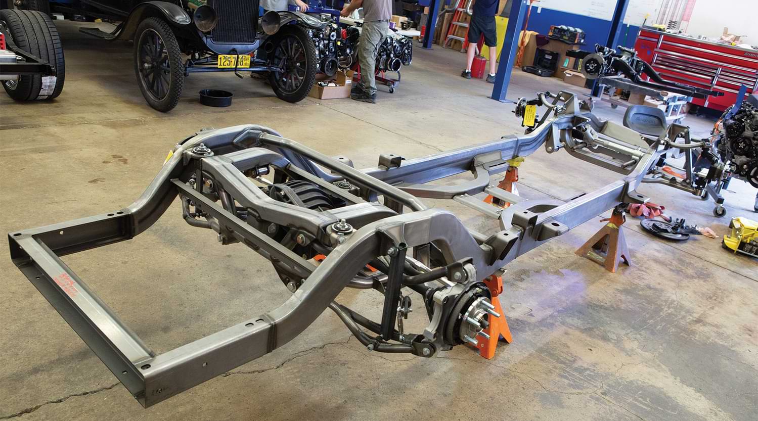
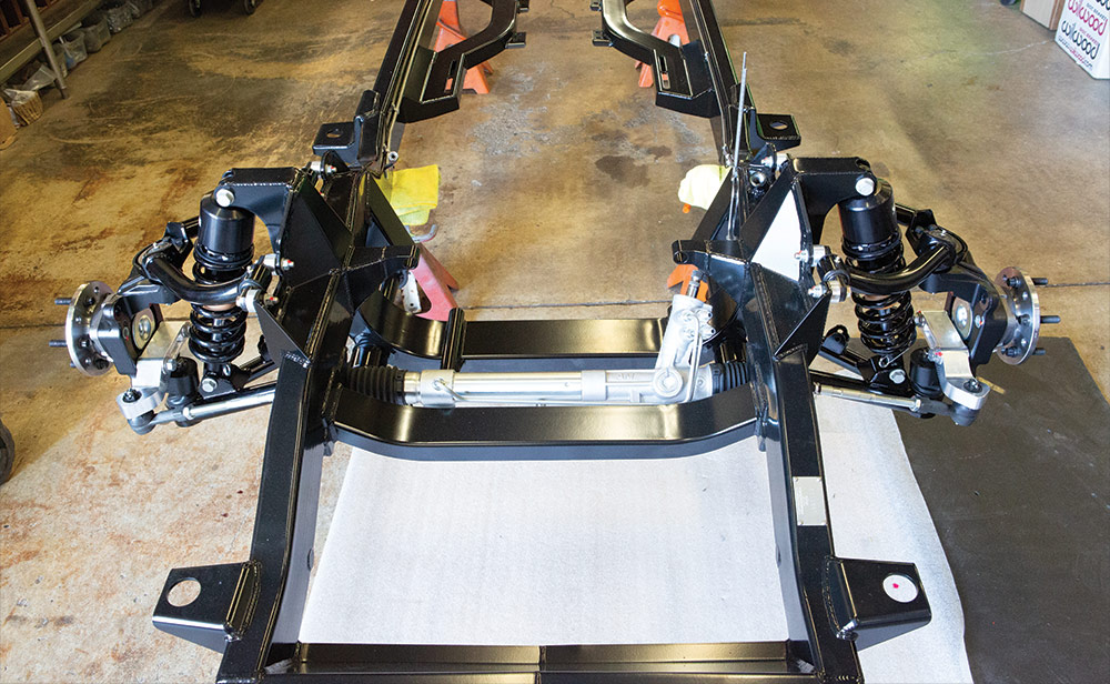
1. Art Morrison (AME) chassis will have the basic suspension components mounted when the chassis arrives.
BY Chadly Johnson Photography BY THE AUTHOR
Photography BY THE AUTHORA
rt Morrison Enterprises (AME) has a brand-new C10 chassis offering, and this is the first one out the door with the IRS upgrade. Let’s take a closer look as the crew at MetalWorks Classic Auto Restoration in Eugene, Oregon, assembles AME’s number one into a roller!
An aftermarket chassis swap can transform your rough-riding ’67-72 C10 into a real joy to drive. Improved ride quality, superior handling, and an aggressive stance are just a few of the improvements your truck will receive. An updated chassis will not only fully enhance your driving performance, but also its durability, dependability, and even resale value.
So, you purchased an AME C10 chassis with an IRS upgrade, congrats, but now what? You might be wondering if the process of tearing the chassis down, getting it coated, and putting it all back together is something you can tackle yourself or should you trust the work to professionals? In this tech feature we give you an overview of the process involved and point out some of the key features of this new design by AME as it’s being assembled by the team at MetalWorks.
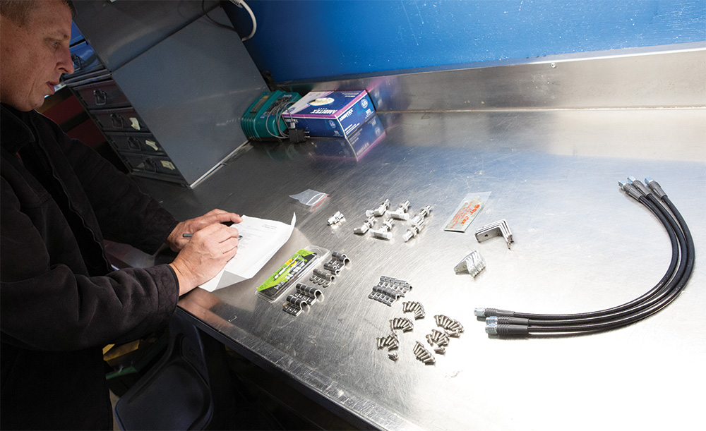
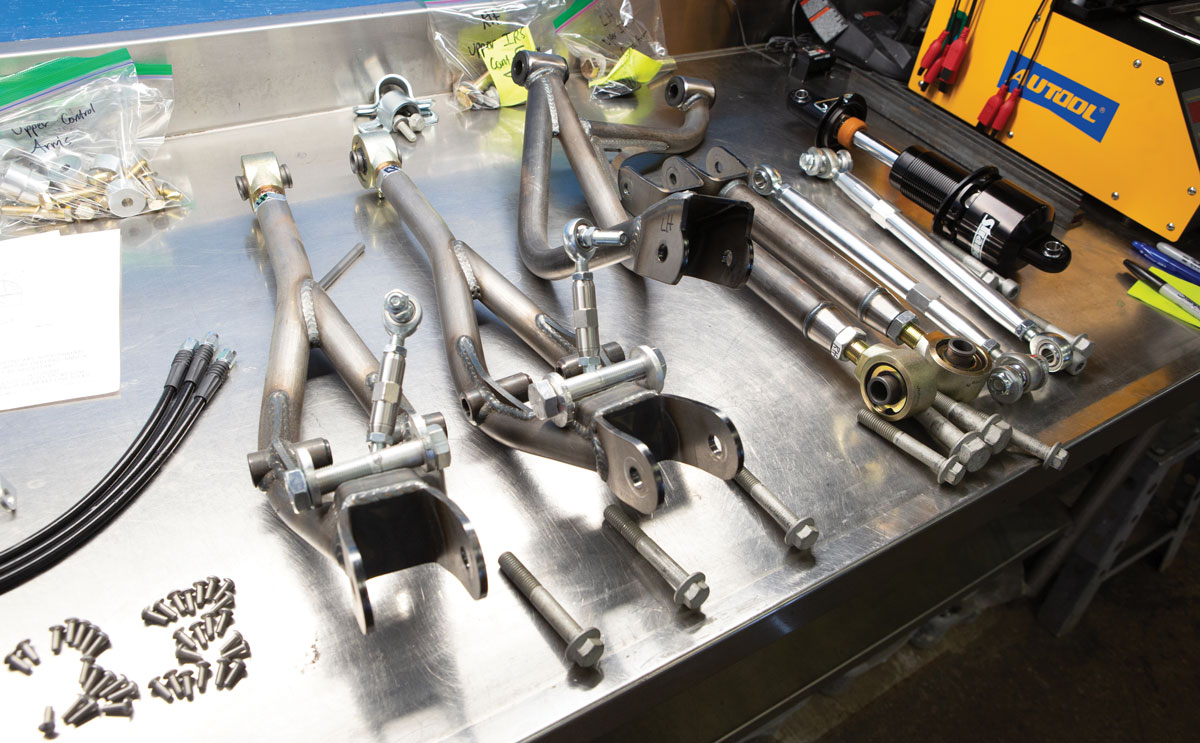
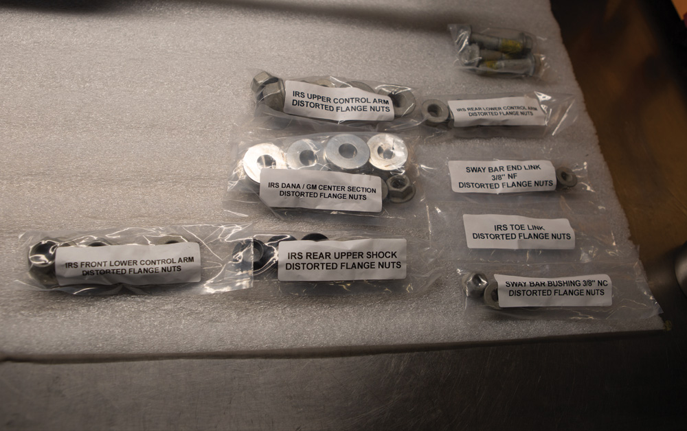
2. Check to make sure you have all the necessary components to assemble your chassis.
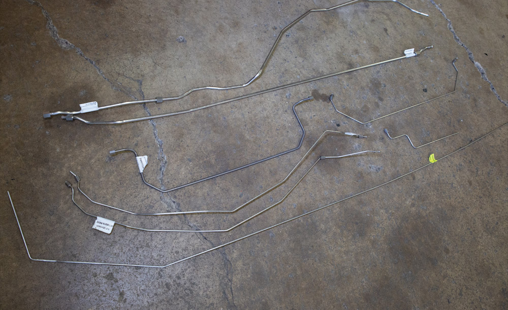
3. AME has pre-bent brake lines to fit their GT Sport chassis. The C10 chassis also includes a -6 fuel line.
4. The stainless steel line kit for this chassis was the first prototype. Because of this, we opted to mock them up by taping lines in place to ensure proper fitment.
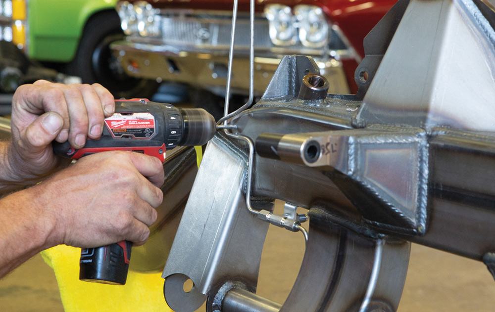
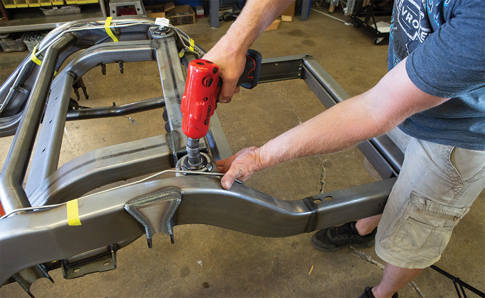
5. Once all the lines are marked, we drill and tap the frame for the brake and fuel line mounts.
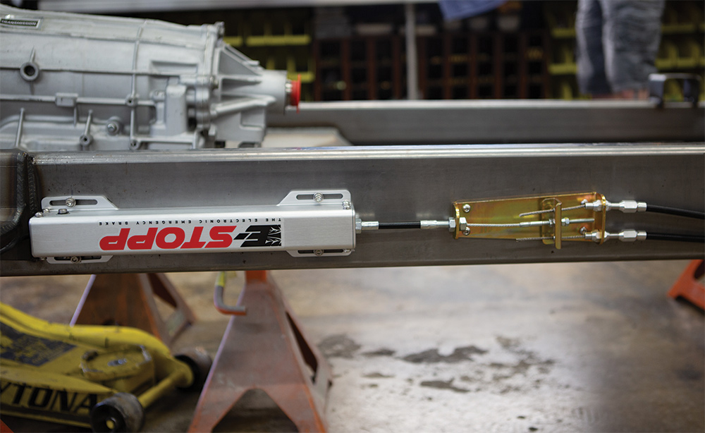
6. The stainless line kit and any additional hardware, such as this electronic E-Stopp, should be mounted before coating to prevent damage to the finish.
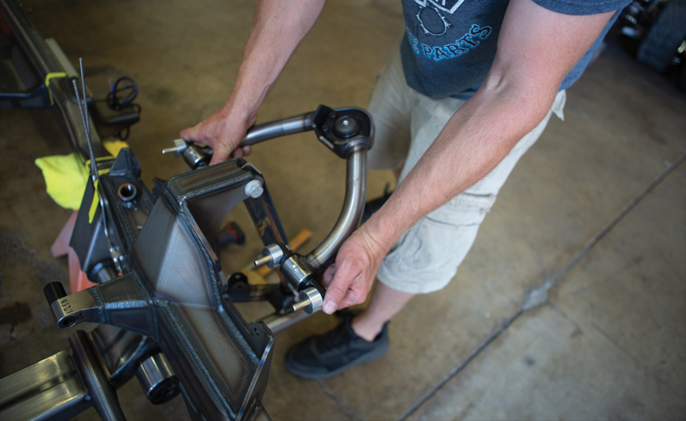
7. Remove front suspension components to prepare for coating.
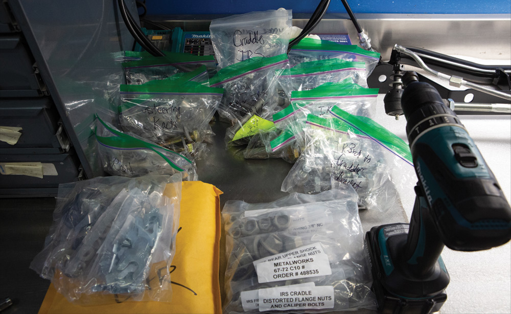
8. Make sure to bag and mark fasteners that are removed from the chassis.
9. You will notice the IRS suspension will have spacers in the control arm mounts. These spacers should be bagged and marked to ensure that they are re-installed in the correct location.
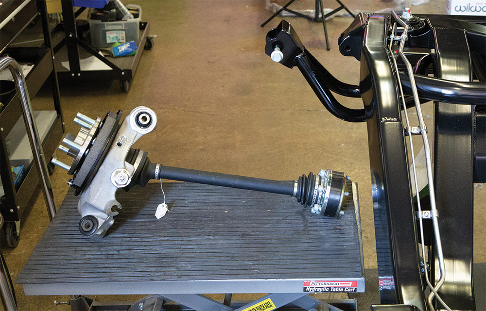
10. Remove the axle shaft and spindle as one unit.
11. Components removed from the IRS in preparation for coating.
12. The IRS will come with various offset washers to allow for pinion angle adjustment.
13. Here we see the IRS cradle being removed. You will notice we add locator rings on the cradle mounts to help locate the cradle when re-installing.
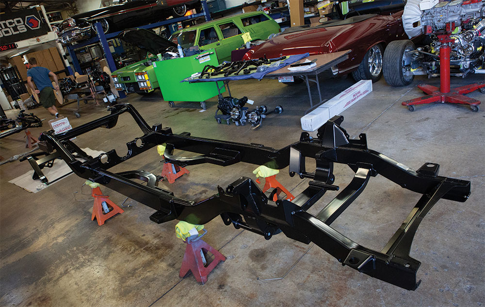
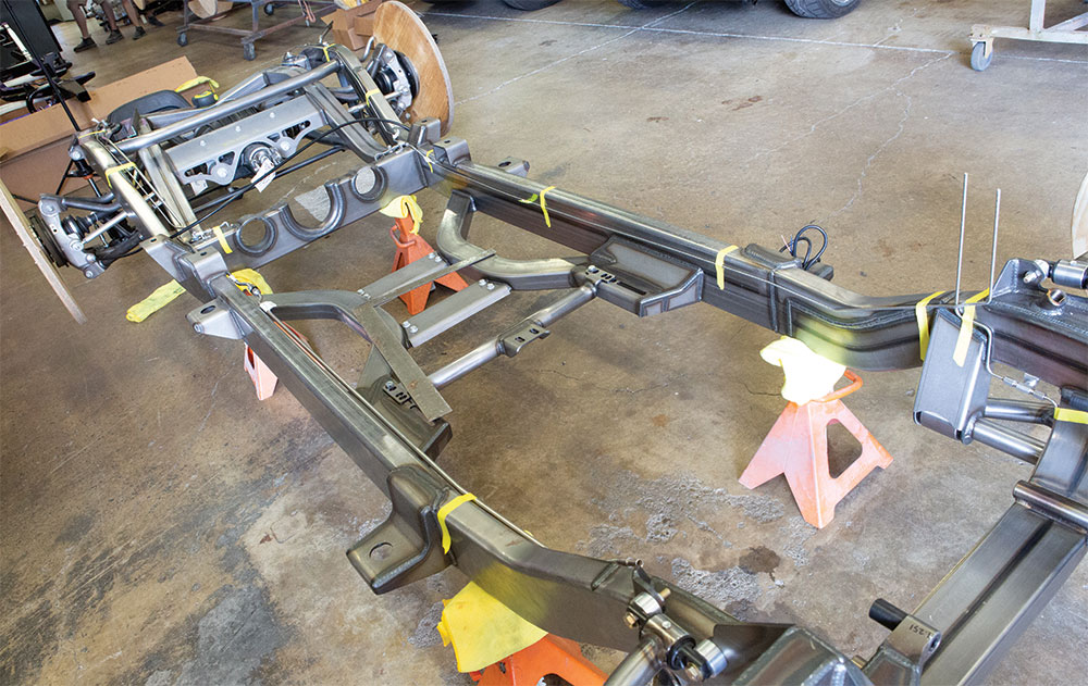
14. Chassis and suspension components coated and ready for reassembly.
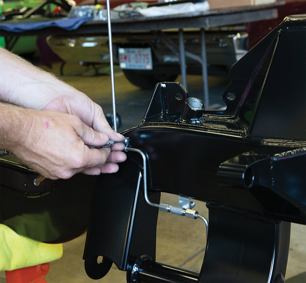
15. Begin reassembly by installing the brake and fuel lines.
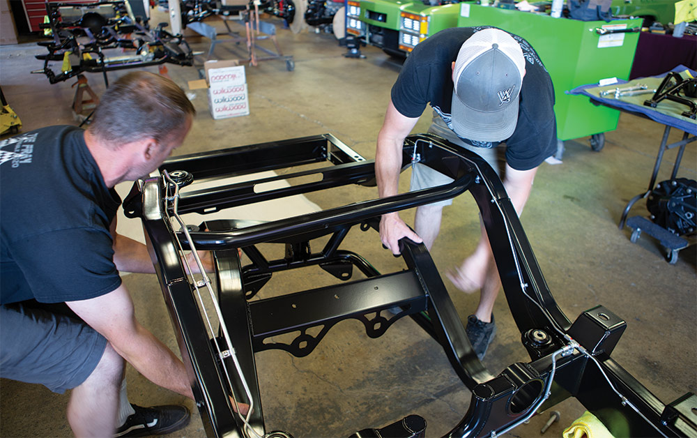
16. Positioning the IRS cradle for installation.
17. The chassis is shipped with temporary nuts installed. The correct nuts will be used when assembling after coating.
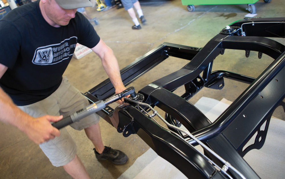
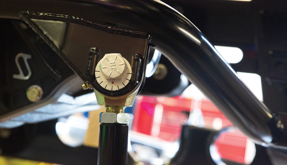
18. Torque fasteners; AME provides a torque specification sheet for all fasteners.
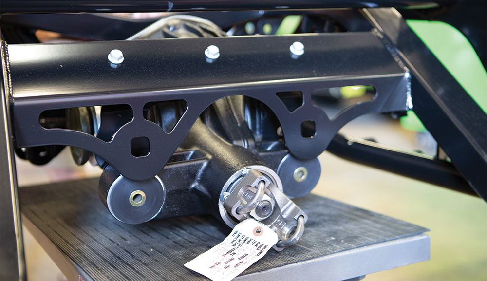
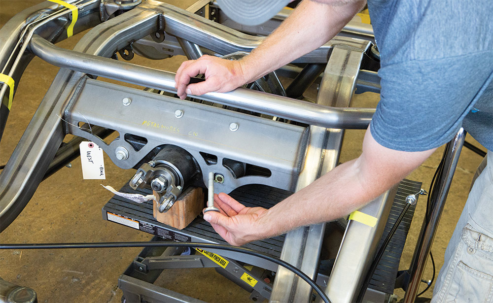
19. Using a lift table will help position the Strange Dana 60 centersection.
20. The IRS will have concentric washers for aligning the rear suspension.
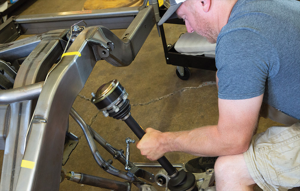
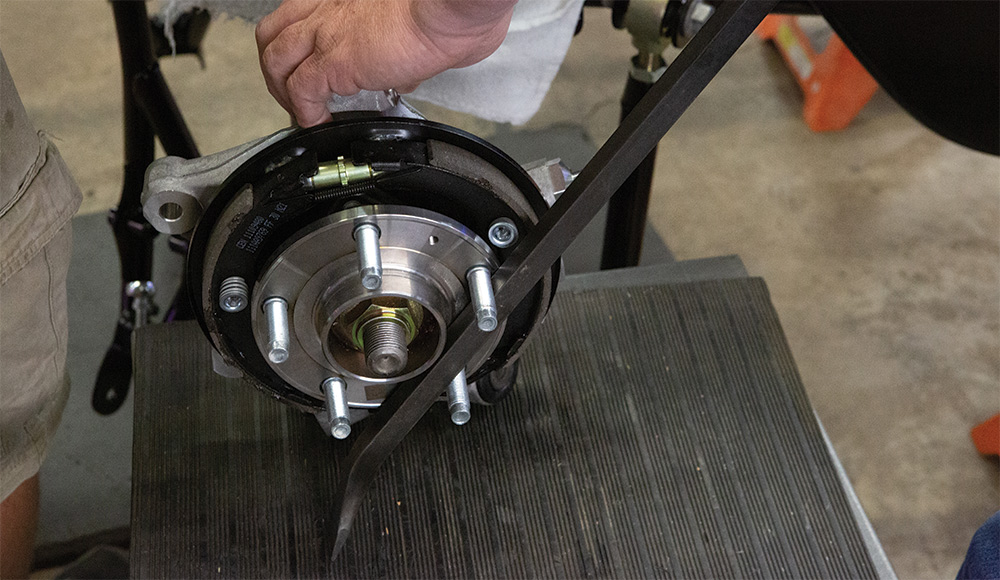
21. Axle and spline assembly ready to be reinstalled.
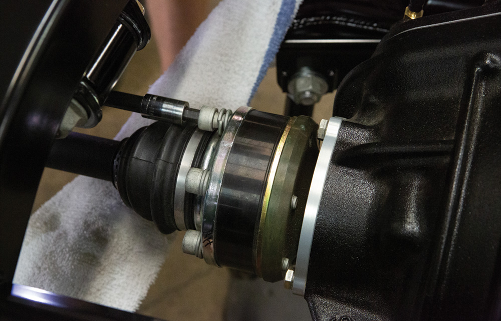
22. Mounting the axle shaft to the centersection.
23. Have an assistant hold the axle while tightening axle bolts to the centersection.
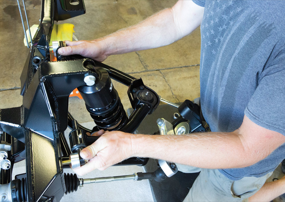
24. Install the control arms.
25. Install the coilovers. You will notice the reservoir is on the bottom. This is done for fitment and will not affect the shock performance.
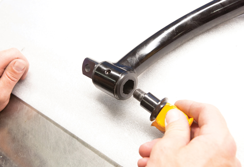
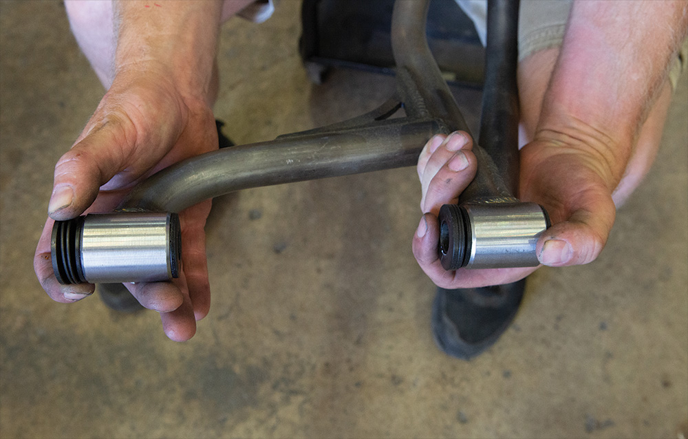
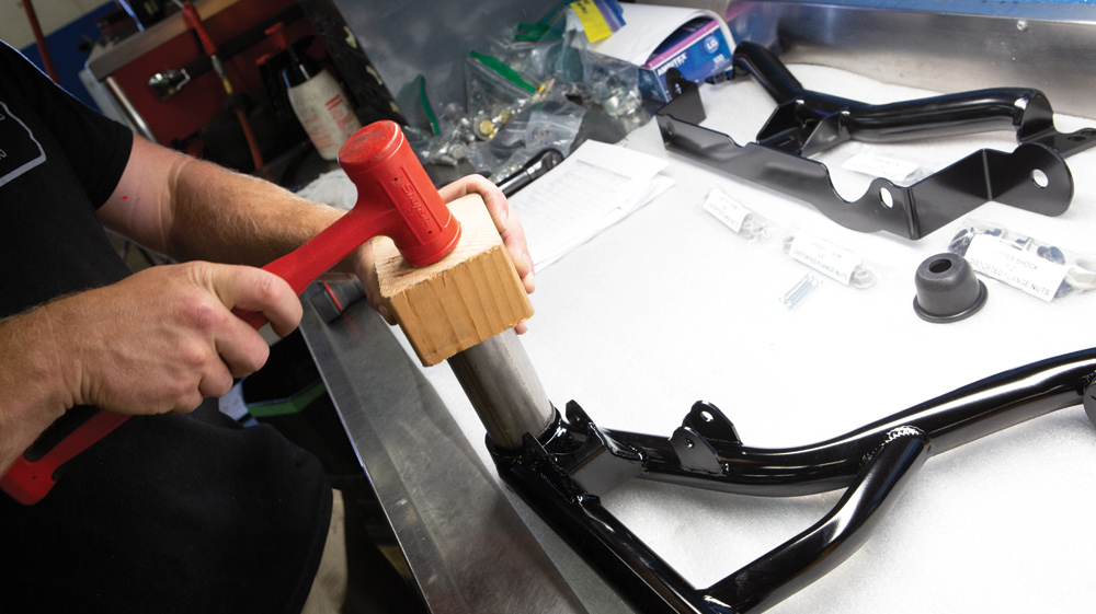
26. Front control arm bushing being reassembled after coating.
27. Reinstall the ball joints after coating.
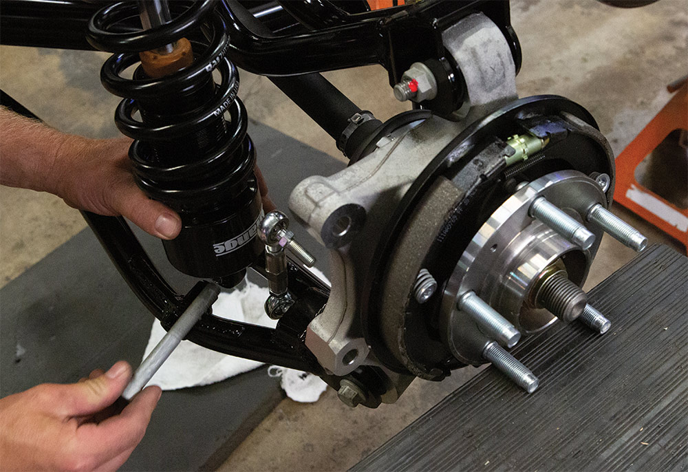
28. A piece of tubing is used to install the ball joint boots.
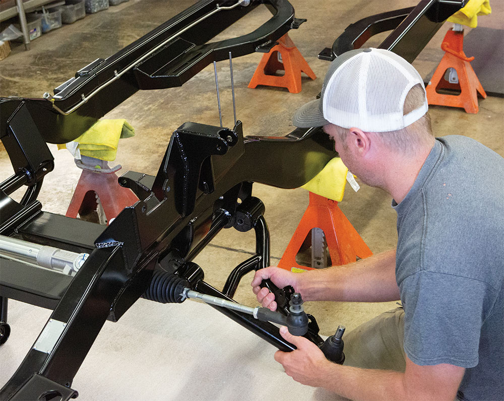
29. Begin assembly of the front suspension.
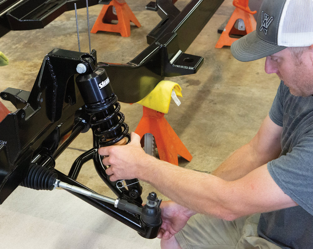
30. Install the front coilovers.
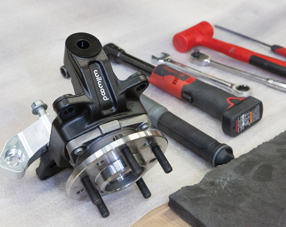
31. AME uses a Wilwood C10 truck spindle on their chassis.
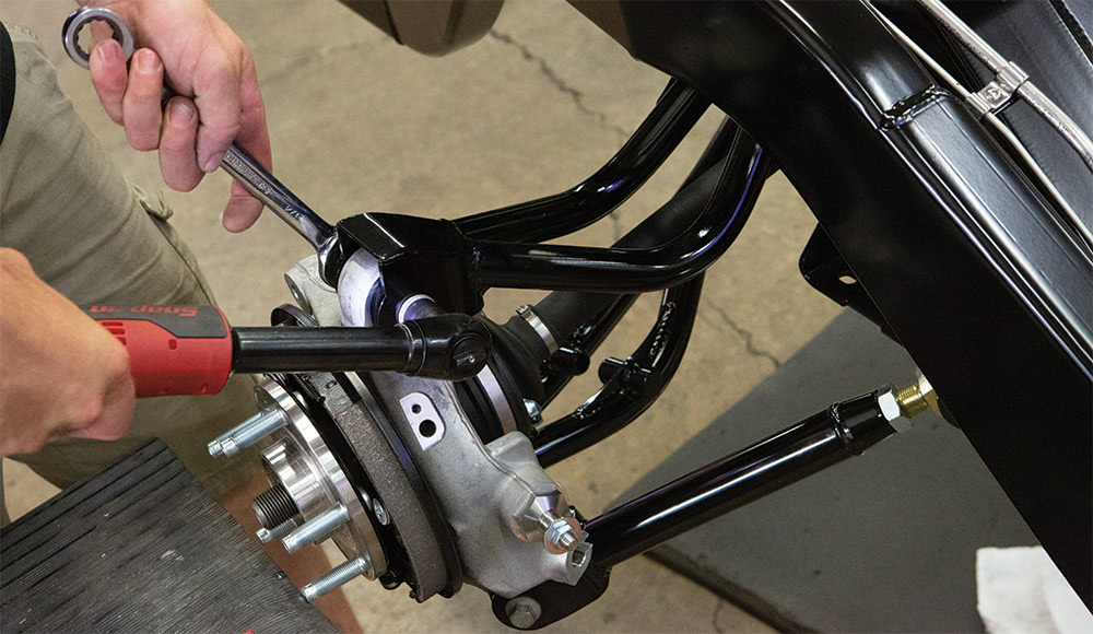
32. Un-bolt the steering arm to provide space to torque the ball joint mount nut.
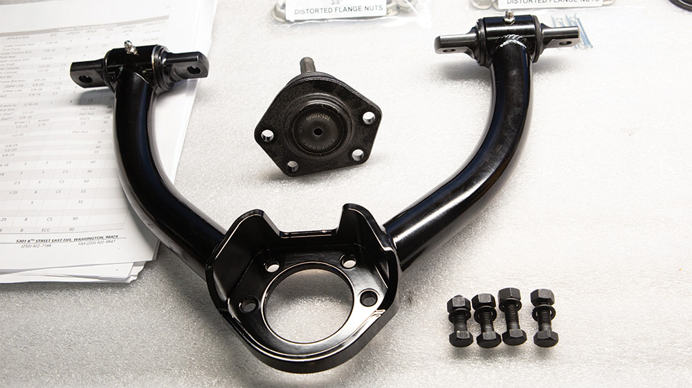
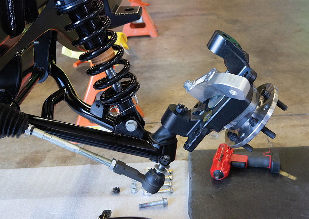
33. Install the upper control arm; make sure spacers are in the correct position.
34. Torque and make all fasteners.