CTP logo Tech
InTheGarageMedia.com
Shifty Business Title
Wrapping Up the ’67 F-100 Overdrive Swap: Trans Linkage & Throttle Upgrade
BY Rob Fortier  Photography and Videography by Ryan Foss
I

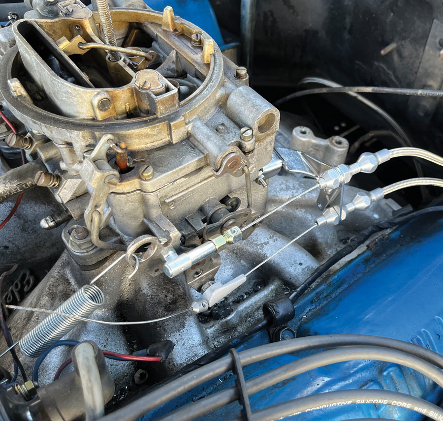
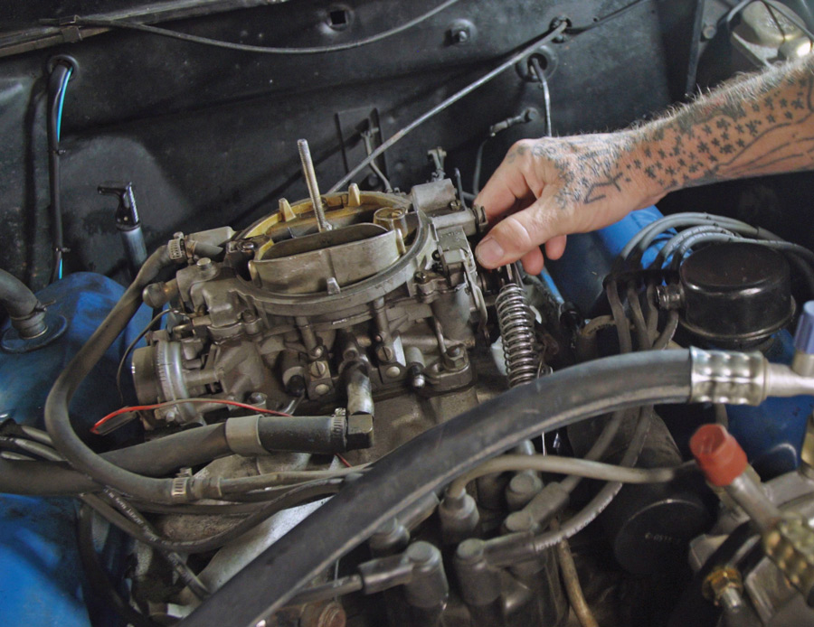
f the sacrilegious marrying of the GM 200-4R behind the 360 FE in our ’67 F-100 last month didn’t scare (piss) you off, welcome back for the install wrapup! We left a couple important items unattended to, namely the manner in which to operate the freshly implanted overdrive transmission, but also the manner in which to accommodate said OD’s kickdown (TV cable) in relation to the throttle actuation.

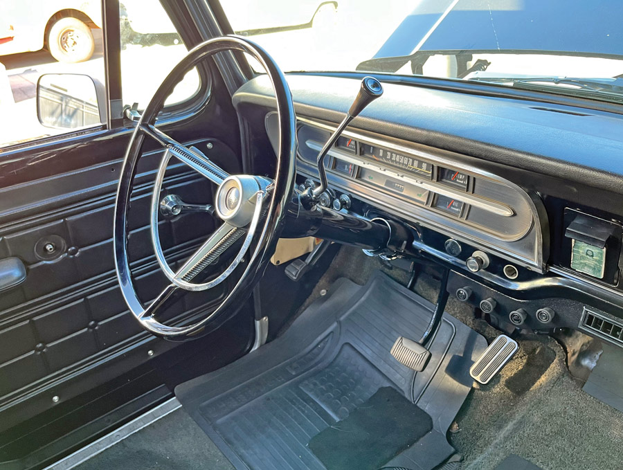
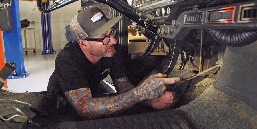
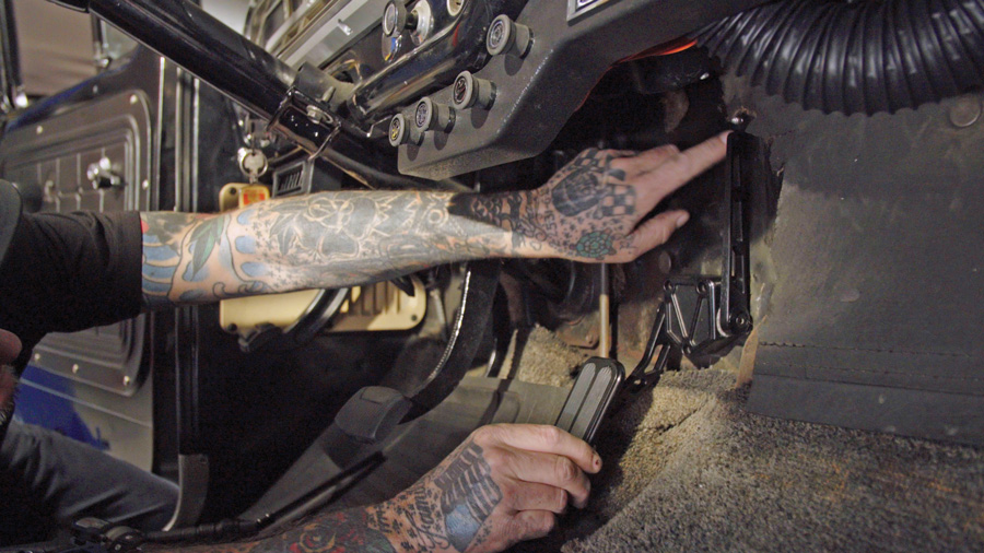
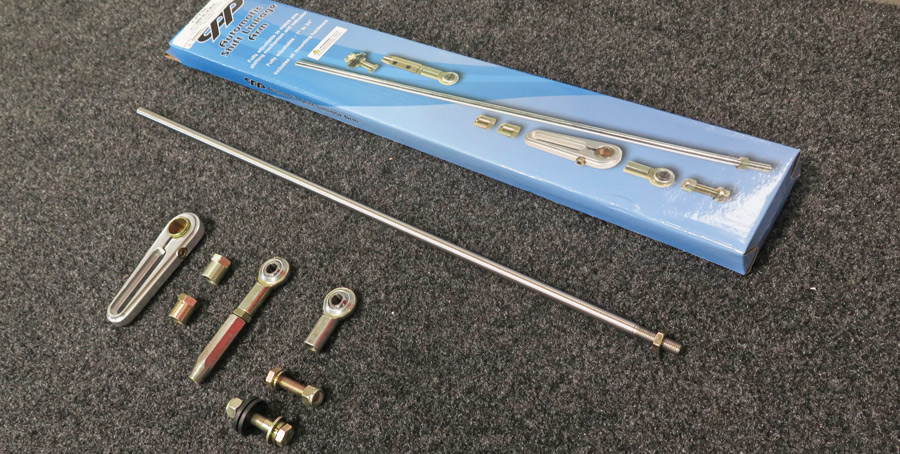
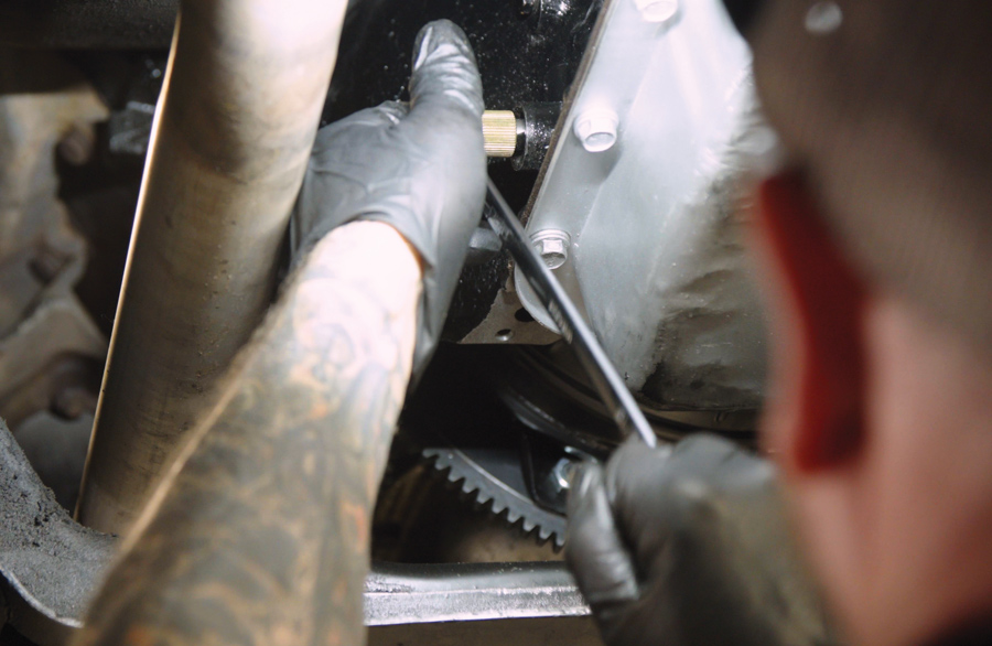
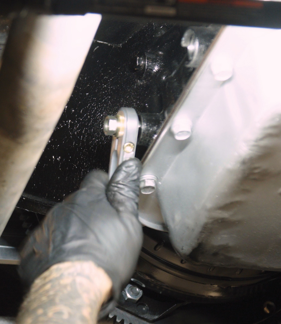
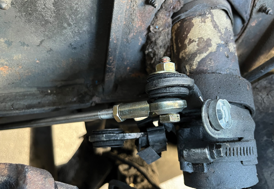
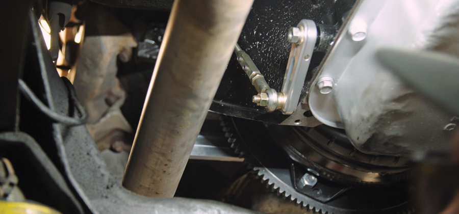
While a brand-new automatic shifter–equipped column for the ’67-and-up F-100s is in the works at Classic Performance Products (CPP), we wanted to utilize the existing manual trans column using CPP’s “universal” automatic shift linkage arm kit so that we could enjoy the fruit of the overdrive labor in the meantime. The slight downside to this method of making do is not having the detent for gear selection built into the column shifter, as it was designed originally for automatic (late-model/aftermarket) column swaps. However, the transmission’s integral shifter detent (along with proper linkage setup and adjustment) will help ensure you stay in the gear you select!

Now, to address the F-100’s factory “push-style” throttle linkage in order to facilitate the 200’s “pull-style” TV (kickdown), we procured a Lokar throttle pedal kit to complement their braided stainless TV cable and bracket used in the trans swap. Unlike your later overdrive transmissions, the 700/200 family of ODs can be run without a transmission control unit (TCU), however, as opposed to a traditional kickdown cable, the TV must be adjusted accurately (and a trans pressure adjustment is highly recommended, if at all possible) to ensure the life of your new overdrive. (One of the biggest killers of GM overdrives are incorrectly adjusted TVs!)

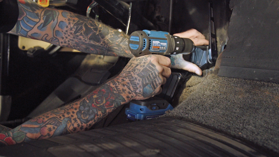
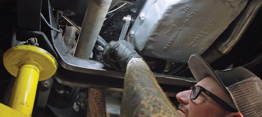
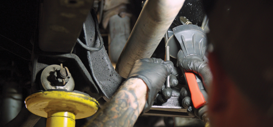
With (all) that said, how about we button up this bipartisan Bowtie/Blue Oval transmission swap once and for all!

’67 F-100 Interior
’67 F-100 Transmission
1-2. The finishing touches required to wrap up our overdrive trans swap in the ’67 F-100 involved converting the stock three-on-the-tree manual shift column to operate the new 200-4R (using Classic Performance Products’ shift linkage kit) and installing a Lokar throttle pedal to accommodate their pull-style TV cable kit already installed (the factory throttle is a push-style configuration).
The stock pusher pedal linkage and its pedal were removed from the equation altogether as they simply go “against” what our TV cable needs to do: pull!
3. The stock pusher pedal linkage and its pedal were removed from the equation altogether as they simply go “against” what our TV cable needs to do: pull!
Locating mounting holes for the pedal
Drilling the mounting holes
4-5. Our new Lokar C10 (PN XBAG-6165) throttle pedal assembly (goes with the whole GM trans swap theme!) was mocked up in its proposed location for mounting holes to be drilled, which took all but a couple minutes.
access for the throttle cable was drilled
drilling a hole for the pedal mount
6-7. Next, with the pedal assembly mounted, the access for the throttle cable was drilled in the firewall directly adjacent to the pedal’s adjustable throttle arm.
The more laborious part was setting up the Lokar Duo-Pak braided stainless throttle cable assembly, which must be cut to fit each application. It will locate between the firewall and the throttle cable bracket on the carburetor.
8. The more laborious part was setting up the Lokar Duo-Pak braided stainless throttle cable assembly, which must be cut to fit each application. It will locate between the firewall and the throttle cable bracket on the carburetor.
If you’ve ever dealt with a stainless fuel line, you’ll have no problem cutting the braided housing to length … if not, a roll of electrical tape and a cutoff wheel with a thin metal-cutting disc will do the trick. Measure the length required. Wrap the housing at the cut mark with tape (a single layer). Then, carefully cut and reinstall aluminum adjuster ferule.
9. If you’ve ever dealt with a stainless fuel line, you’ll have no problem cutting the braided housing to length … if not, a roll of electrical tape and a cutoff wheel with a thin metal-cutting disc will do the trick. Measure the length required. Wrap the housing at the cut mark with tape (a single layer). Then, carefully cut and reinstall aluminum adjuster ferule.
Also, make sure you deburr the Teflon liner and lubricate the housing before reinserting the throttle cable.
10. Also, make sure you deburr the Teflon liner and lubricate the housing before reinserting the throttle cable.
With the housing cut and adjuster ferules installed, it can be mounted in place between the carb and firewall; we left plenty of room for cable tension adjustment.
11. With the housing cut and adjuster ferules installed, it can be mounted in place between the carb and firewall; we left plenty of room for cable tension adjustment.
Running the (un-cut) throttle cable through the lubed housing from the interior side
Attaching the cable with the provided pin and C-clip
12-13. Run the (un-cut) throttle cable through the lubed housing from the interior side, as the attachment for the pedal is pre-installed and, well, we want to keep it that way! Attach the cable with the provided pin and C-clip.
The cable can being trimmed
ready to install the provided cable end assembly
14-15. The cable can be trimmed (with a good set of sharp heavy-gauge wire cutters) once you’ve set your slack and are ready to install the provided cable end assembly.
All sarcasm aside, the C10 direct-fit throttle assembly was a perfect fit in the F-100.
16. All sarcasm aside, the C10 direct-fit throttle assembly was a perfect fit in the F-100.
With the throttle cable set and the return spring installed, the TV cable was reset accordingly (you want no cable slack at WOT).
17. With the throttle cable set and the return spring installed, the TV cable was reset accordingly (you want no cable slack at WOT).
As mentioned, we’re retaining the F-100’s manual trans column (for now) and using CPP’s CPTSL Automatic Shift Linkage Arm kit to actuate our 200-4R overdrive. It’s a universal kit that can—and will—be modified and fit to suit our hybrid application.
18. As mentioned, we’re retaining the F-100’s manual trans column (for now) and using CPP’s CPTSL Automatic Shift Linkage Arm kit to actuate our 200-4R overdrive. It’s a universal kit that can—and will—be modified and fit to suit our hybrid application.
The splined (gold) bushing attaches to the transmission’s selector shaft
 it allows the aluminum shifter arm to be set in multiple locations to accommodate varying linkage configurations.
19-20. The splined (gold) bushing attaches to the transmission’s selector shaft (which is set to Park for setup/installation); it allows the aluminum shifter arm to be set in multiple locations to accommodate varying linkage configurations.
In order for the shifter rod to connect to our stock column free and clear of any obtrusions (exhaust, the trans itself, and so on), Jason Scudellari eyeballed the travel path between the transmission and the steering column linkage arm.
21. In order for the shifter rod to connect to our stock column free and clear of any obtrusions (exhaust, the trans itself, and so on), Jason Scudellari eyeballed the travel path between the transmission and the steering column linkage arm.
He then formed the required dog leg in the solid stainless shift rod the old-fashioned way—by hand in the vise!
22. He then formed the required dog leg in the solid stainless shift rod the old-fashioned way—by hand in the vise!
The rod was attached to the column as shown (the reverse lever was left intact, as it did not interfere with anything) and the column shifter secured in the park position …
23. The rod was attached to the column as shown (the reverse lever was left intact, as it did not interfere with anything) and the column shifter secured in the park position …
… then the shift rod was cut to fit on the transmission end using a cutoff wheel.
24. … then the shift rod was cut to fit on the transmission end using a cutoff wheel.
The supplied heim adjuster was installed along with the adjustable hex connector onto the newly formed shift rod, which was then attached to the transmission.
25. The rod was attached to the column as shown (the reverse lever was left intact, as it did not interfere with anything) and the column shifter secured in the park position …
Driving the finished ’67
26. The final step was to ensure the adapted manual trans column shifter freely and accurately shifted the 200-4R through all the gears … which it did, with little adjustment of course. As mentioned in the story, CPP is developing direct-fit automatic tilt columns for the later F-100s, which we’ll be installing one we get around to updating the power steering in the ’67. Stay tuned!
Duralast, Harbor Freight, Frontier Logos
CLASSIC PERFORMANCE PRODUCTS
(800) 760-7438
classicperform.com
Lokar
(877) 469-7440
lokar.com
HARBOR FREIGHT
harborfreight.com