CTP logo Tech

InTheGarageMedia.com

Driver's Education typography
1. Paul Wilson tightens up the bracket securing the Flaming River column to the Chevy pickup’s dash. Buddy the shop dog seems to think throwing a tennis ball is equally important.
What You Need to Know About Installing Steering Components
BY Ron Ceridono Images by THE AUTHOR
O

ne of the most difficult things for someone to admit is that after investing time and money in a project that the completed project is no fun to drive. The fact is that even the coolest-looking trucks seldom see the road if the steering wheel placement isn’t comfortable.

When installing a steering column there are several considerations, certainly appearance is one of them. Many years ago steering columns were often sourced from wrecking yards. Those of us who have been around for a while can remember the GM car and truck tilt columns that were so ugly the bottom portion was hidden by carpet or upholstery material. Of course whenever steering components are involved, safety is a concern as well. Years ago, if U-joints were necessary to connect the steering column to the gear there wasn’t much to choose from. We’ve seen U-joints used that were designed for industrial applications, power takeoffs, import car applications, and even some from military surplus stores (most of which were for light helicopter tail rotor driveshafts). Many of these installations were sketchy at best and dangerous at worst.

Thankfully, using junkyard steering parts is no longer necessary as all-new components are available from Flaming River. They offer a complete line of fixed and tilt columns, with or without shifters and with or without ignition switches. Made in the USA, all Flaming River columns are made from 304-grade stainless steel and are available in paintable mill finish, highly polished, or black powdercoated. Column lengths from 17 to 45 inches are available and shafts come in 1-inch Double D as well as 1-inch 48-spline and 3/4-inch 36-spline—basically there’s a Flaming River column for any application. In the case of the 1952 Chevy pickup shown here, we used a mill finish, 32-inch floor shift tilt column (PN FR20006).

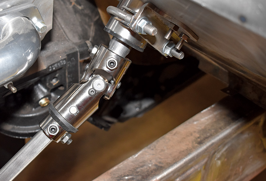
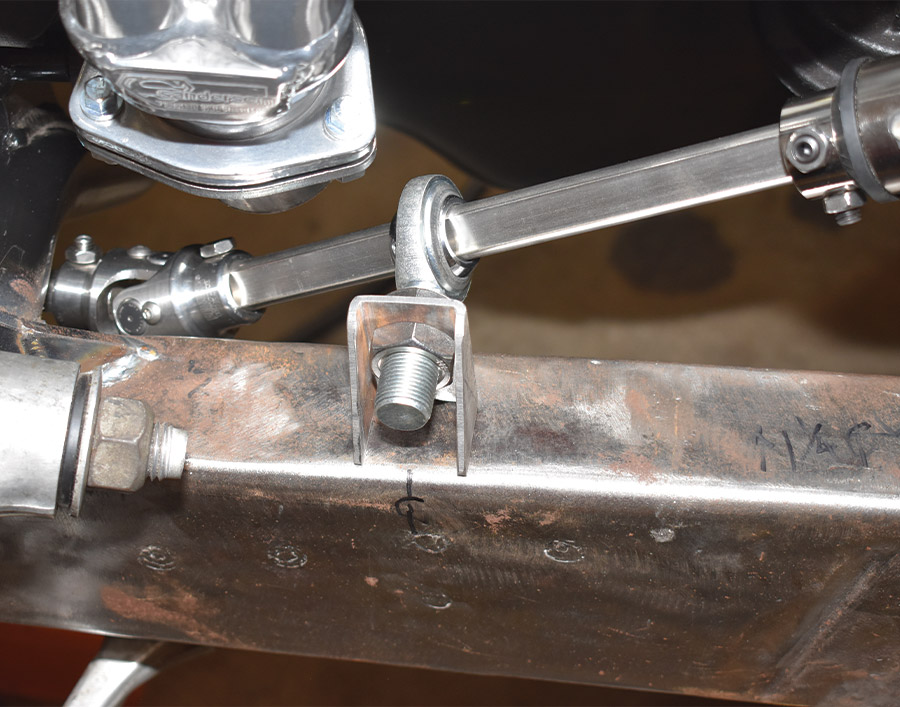
As is often the case, to connect the steering column in our truck to the Corvette rack-and-pinion steering gear three U-joints were required. Be aware that when a steering system contains three U-joints, a support bearing is necessary to keep them from “whipping” (double U-joints and vibration reducers are considered to be two, so at one end of a shaft with a single U-joint at the other requires a support bearing).

Although pinning and welding U-joints to shafts was once common, the preferred method is to use splined or double-D (DD) shafts. Both are strong and safe—splined shafts come in various lengths that can be shortened an inch on each end if necessary. When using splined shafts it is necessary to “clock” the U-joints so the yokes are aligned. DD shafts also come in various lengths and are easily cut to fit. Aligning the U-joints on DD shafts isn’t an issue as they only fit one way.

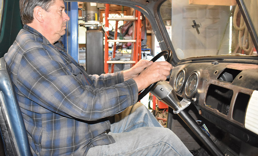
When installing a steering column the position of the steering wheel is critical—if the steering wheel is too far away it puts a strain on the driver’s shoulder muscles; too close and it strains the wrists. Long distance GT racers have found that positioning the steering wheel so their arms are at a 40- to 55-degree angle is ideal to reduce fatigue.

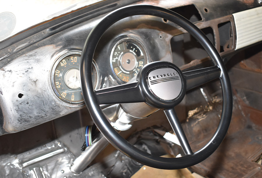
Another often-overlooked consideration when positioning the steering column is the “line of sight” from the driver seat. There are some automotive designers who suggest that the steering column of a performance vehicle should be very slightly angled so as to point at the center of the lane out in front of the vehicle, in other words it follows the driver’s line of sight. Although it is a subjective issue, some drivers claim a vehicle that has had the steering column pointing off to the left of the line of sight is disconcerting. With the steering column, shafts, and U-joints in place, the finishing touch was to add a downsized reproduction 1952 Chevy pickup steering wheel from Speedway Motors and an original-style horn button from Chevs of the 40’s.

When installing steering components safety and appearance are obviously important considerations, but always mock up the steering wheel and column make sure you end up with a truck you really want to drive.
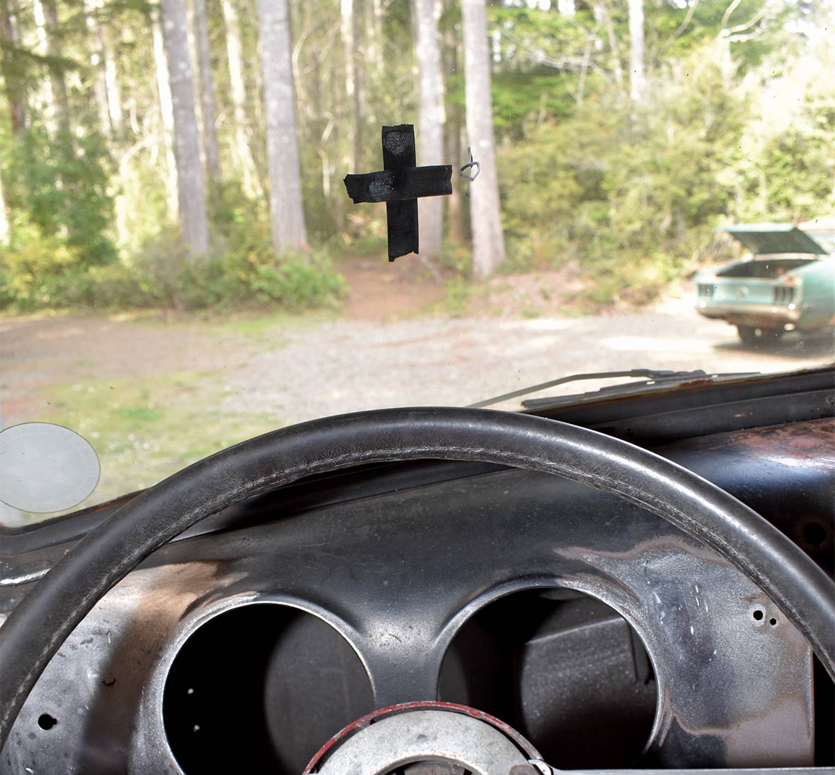
windshield marked with black tape
2. With the seating position determined we marked the windshield at the center of the driver’s line of sight. Then a length of PVC pipe and a steering wheel was used to determine the location of the column.
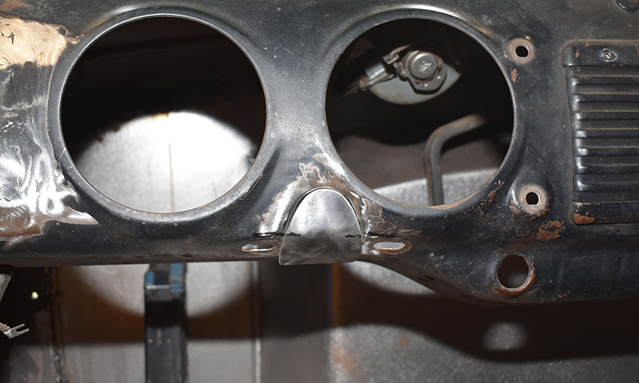
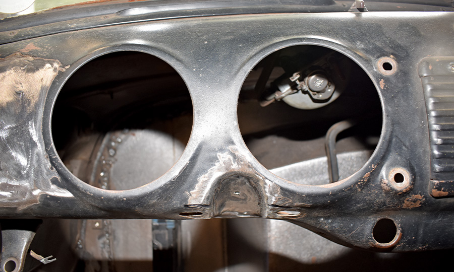
1952 dashboard with a notch to accommodate a column shifter
3. The 1952 dash had a notch to accommodate a column shifter. Note how it isn’t centered between the instrument openings.
dash where steering column bracket would be attached
4. To smooth the dash where the steering column bracket would attach Wilson fabricated a filler panel from sheetmetal.
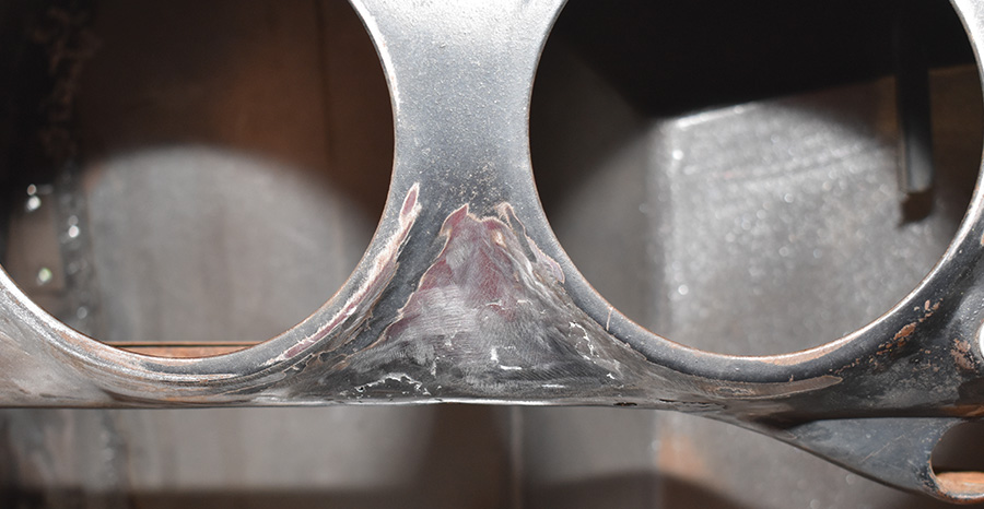
filler panel that has been welded and ground smooth
5. Here the filler panel has been welded and ground smooth.
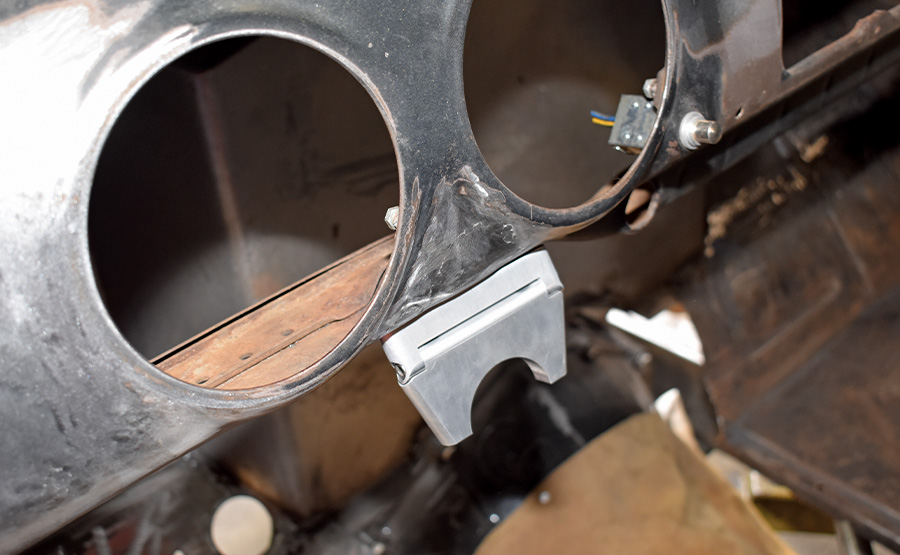
Flaming River 2-1/2-inch billet aluminum column drop
6. To secure the top of the steering column a Flaming River 2-1/2-inch billet aluminum column drop was used (PN FR20107).
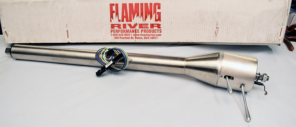
Flaming River tilt floor shift column
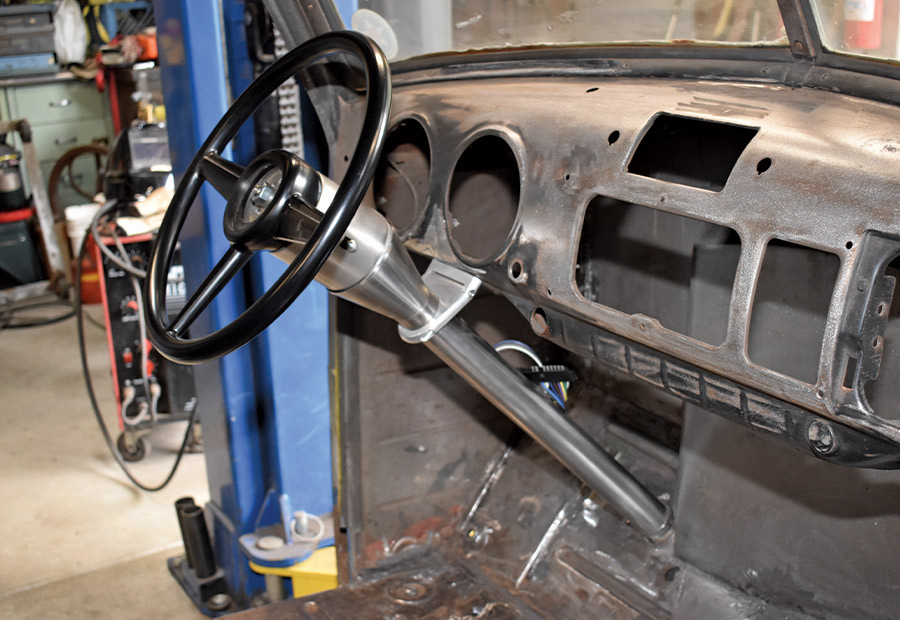
7. The tilt floor shift column has a paintable mill finish and is 32 inches long and 2 inches in diameter. Each column comes complete with a billet dress-up kit (tilt/turn signal levers and hazard knob).
bracket made out of angle iron and a 2-inch muffler clamp
8. To secure the steering column at the bottom Wilson fabricated a bracket out of angle iron and a 2-inch muffler clamp.
closeup of the homemade bracket put in place
9. Here the homemade bracket is in place. When measuring for a steering column consider how far it sticks out of the firewall as that will affect the angle of the upper U-joint. Note the steering shaft in the column is 1-inch DD.
man sitting in the driver's seat and determining a good location for the steering wheel
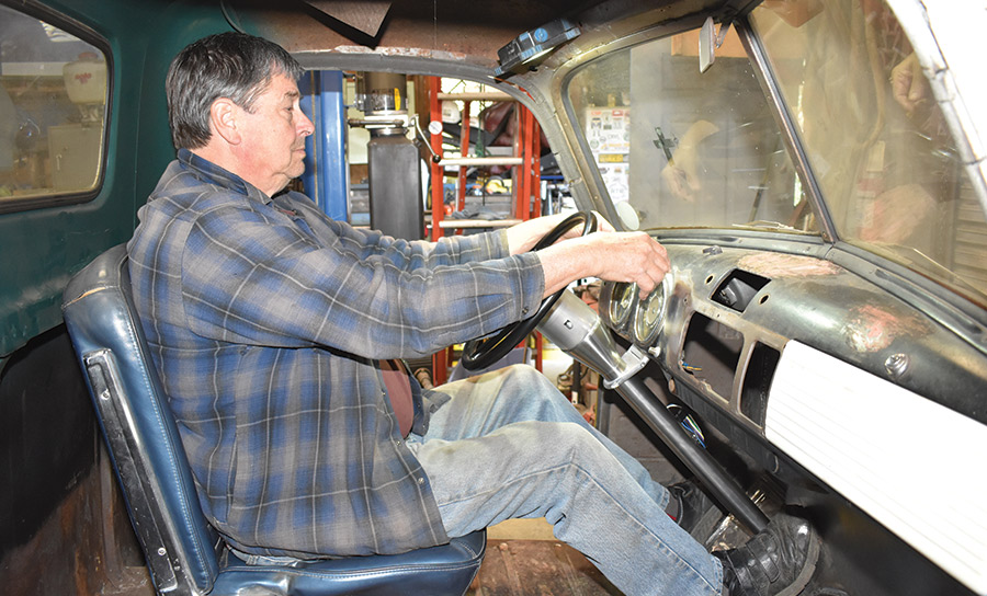
10. Here is a good method to determine the location of the steering wheel. Sitting back in the seat with your arms extended without stretching, your wrists should rest on the steering wheel.
man holding onto steering wheel
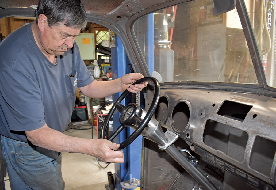
11. With the steering wheel’s position determined, the driving position is ideal with just enough bend in the arms.
stem for the horn button
12. Before installing the steering wheel the canceling cam must be timed or the turn signals will not cancel correctly. The stem for the horn button should clocked at the 10:30 position as shown for the turn signals to cancel as they should.
black 15-inch-diameter reproduction of the original ’47-54 Chevy truck steering wheel
13. For a steering wheel Wilson chose a black 15-inch-diameter reproduction of the original ’47-54 Chevy truck steering wheel from Speedway Motors (PN 910946).
Speedway steering wheel bolted directly onto the Flaming River column
14. The Speedway steering wheel bolts directly onto the Flaming River column without an adapter.
reproduction horn button being installed onto steering wheel
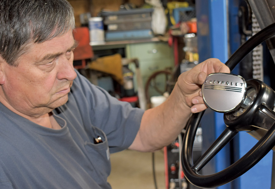
15. To top off the stock-style steering wheel a reproduction horn button was ordered from Chevs of the 40’s.
view of the steering wheel
16. To simplify wiring our Flaming River column came with GM color-coded wiring with a 4-1/4-inch connector.
pieces of PVC pipe taped together to mock up the steering shafts and U-joints from the column to the rack-and-pinion
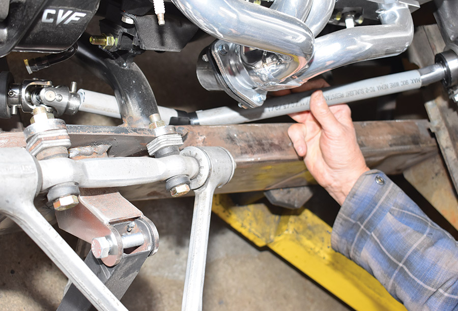
17. We used pieces of PVC pipe taped together to mock up the steering shafts and U-joints from the column to the rack-and-pinion (the shaft isn’t as close to the header as it appears in the photo).
three U-joints, two 3/4 DD shafts, and a support bearing
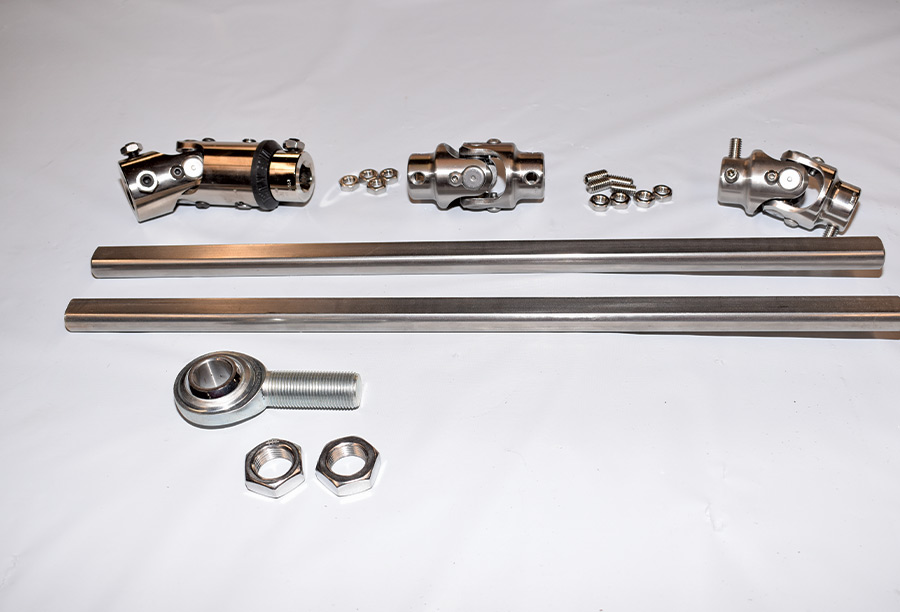
18. To connect the column to the rack-and-pinion three U-joints, two 3/4 DD shafts, and a support bearing were required.
closeup of the steering column
19. At the steering column we used a 1-inch DD x 3/4-inch DD vibration reducer (PN FR1896) to absorb vibration from the steering system. These use a bushing system of thermoplastic material that is resistant to oil, salt, and weather conditions.
homemade bracket mounts a Flaming River zinc-plated 3/4-inch support bearing
20. As three U-joints were used a support bearing was required. The homemade bracket mounts a Flaming River zinc-plated 3/4-inch support bearing (PN FR1810).
middle of the two steering shafts is a 3/4 DD x 3/4 stainless steel U-joint
21. The middle of the two steering shafts is a 3/4 DD x 3/4 stainless steel U-joint (PN FR2516DD). The Corvette rack-and-pinion is connected by a 17mm DD x 3/4 DD stainless steel U-joint (PN FR2559DD).
transfer punch being used to make indentations 7/8 inch from the ends of the shafts
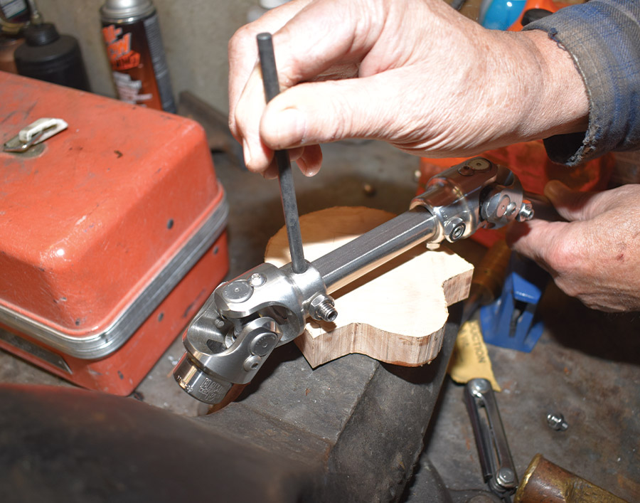
22. With the DD shafts cut to fit a transfer punch was used to make indentations 7/8 inch from the ends of the shafts.
indentations were countersunk to accept setscrews
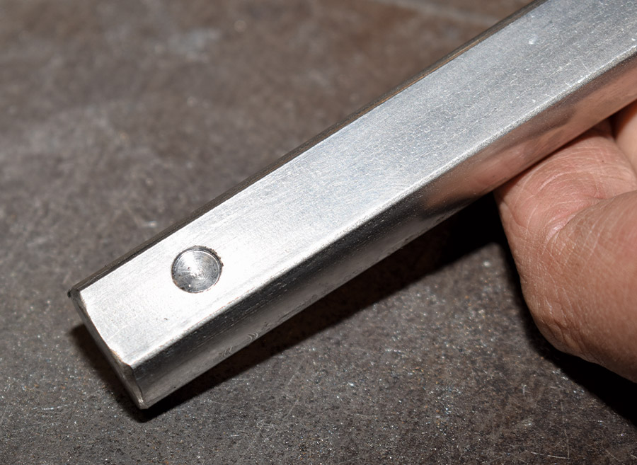
23. Using a 1/4-inch drill bit, the indentations were countersunk to accept setscrews. Red thread locker is applied to the setscrews that are tightened to no more than 25 lb-ft, then the lock nuts are secured.
SOURCES