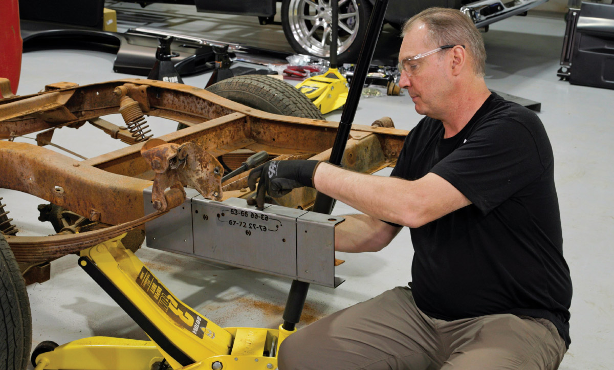
CTP Tech
InTheGarageMedia.com
Danny Nix positioning the template that will serve as a guide to cut a longbed GM frame down to shortbed size
1. Classic Performance Products (CPP) engineer Danny Nix positions the template that will serve as a guide to cut a longbed GM frame down to shortbed size.
A Short Story
Cutting a 1963-72 Longbed Chevy/GMC Down to Size
BY Ron CeridonoImages BY CTP Staff
I

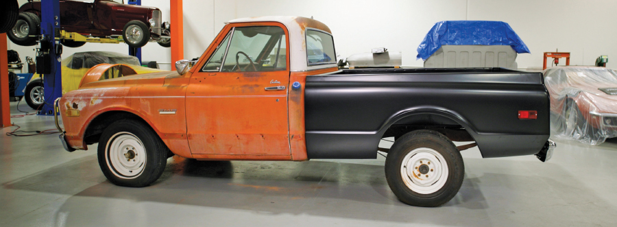
n the July ’24 editorial in Classic Truck Performance magazine, editor Rob Fortier covered the controversy concerning the conversion of a longbed C10 pickup into a shortbed. As always Rob looked at both sides of the issue while pointing out that General Motors sold far more longbed trucks than shortbeds, something like three times as many between 1967 and 1972. That fact is a good argument for cutting a longbed down to size.

Like many things, how pickup trucks are viewed today is far different from the ’60s and ’70s. Back then pickup trucks were simple, rugged utilitarian vehicles so it stands to reason that so many buyers opted for longbeds due to their increased carrying capacity. As a result, after years of service, many longbed trucks have the telltale signs of leading a rough life.

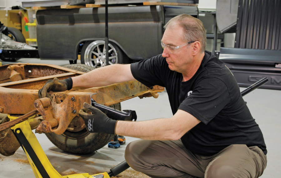
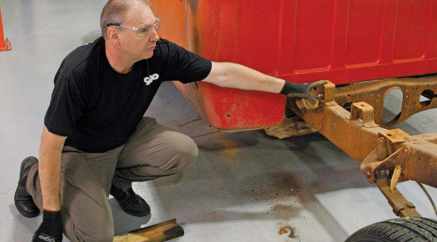
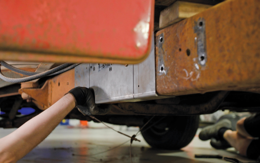
Although longbed Chevy and GMC trucks have their followers, there’s no question that the shortbed versions are more popular with classic truck fans. Of course supply and demand being what it is, the more sought-after shortbed trucks bring higher prices when compared to longbeds, but that lower initial investment can be an advantage in some instances, particularly when an affordable Classic Performance Products (CPP) frame shortening kit (PN 6372LBCSK) is considered.

While the thought of cutting a frame in two can be intimidating, CPP’s longbed frame shortening kit was designed with the do-it-yourself enthusiast in mind with basic hand tools and good jackstands. A pair of simple templates are provided for drilling and cutting the frame and bobbing the back of the ’rails.

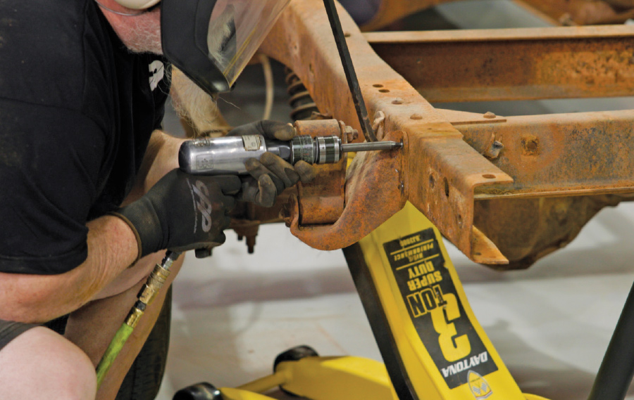
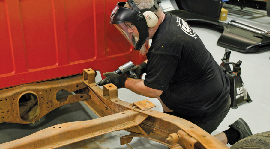
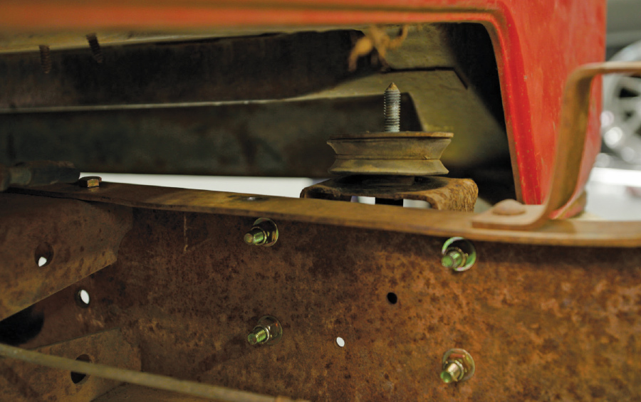
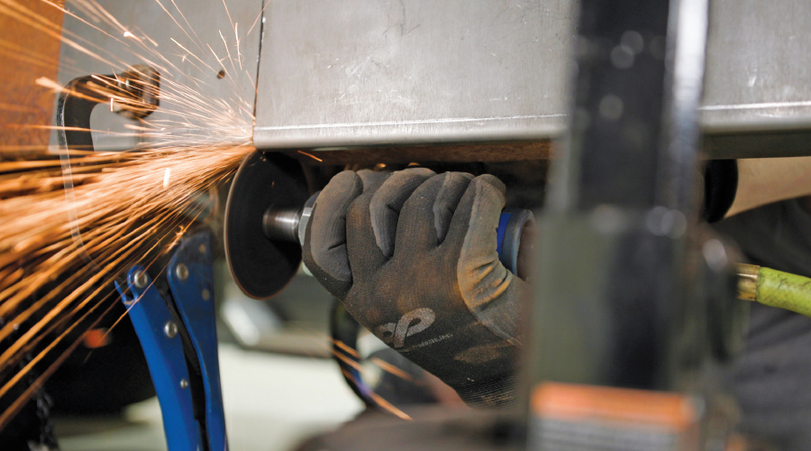
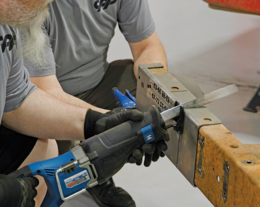
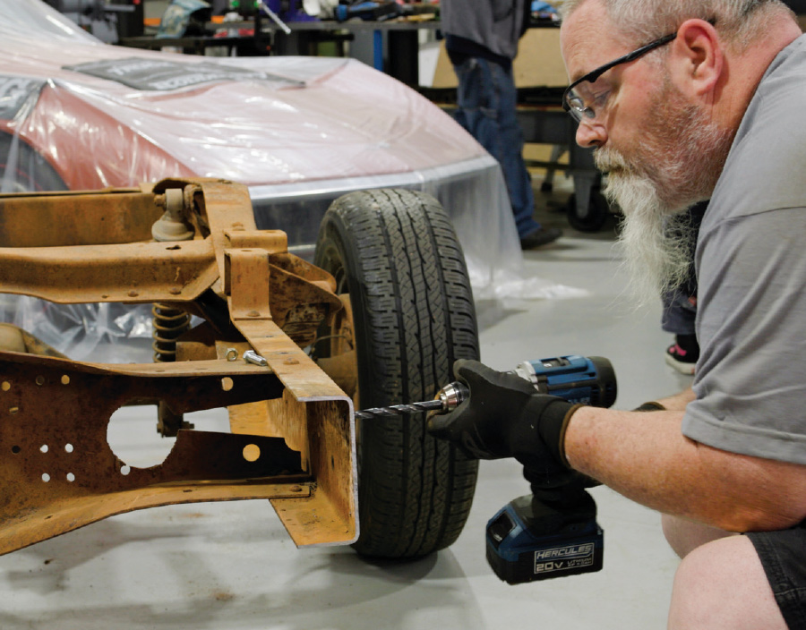
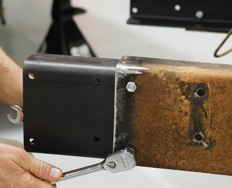
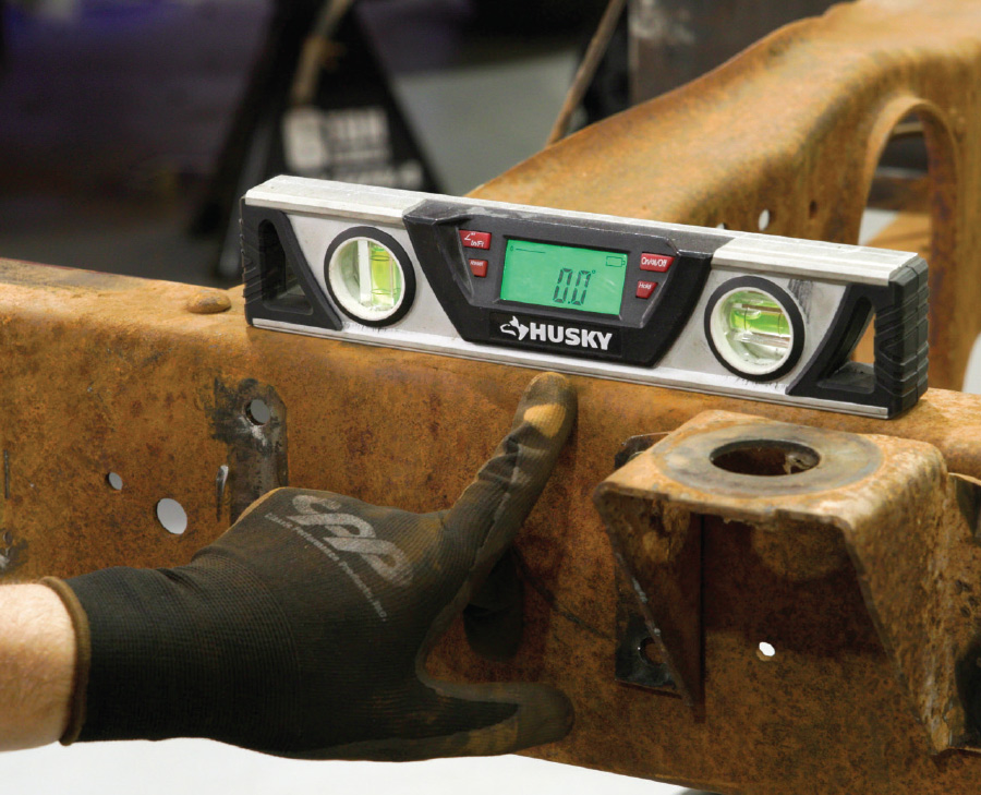
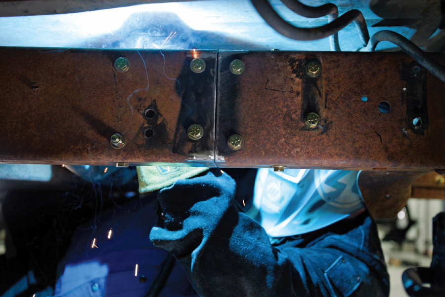
Once the frame is shortened by removing a section under the cab, it is put back together with laser-cut C-channel reinforcements that are bolted in place (CPP does recommend welding as well to ensure long-term structural rigidity). Included in the kit are step-by-step instructions on how to modify the frame and all the necessary hardware.

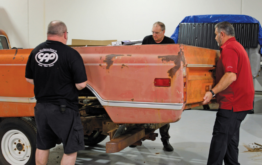
Now that the chassis modifications are complete, next time we’ll wrap up our short story by showing how to assemble a new short Fleetside pickup box.

well-used GMC longbed pickup
2. This is what we started with, a well-used GMC longbed pickup. These trucks are generally more affordable than their shorter siblings.
CPP’s shortening kit on longbed pickup
3. CPP’s shortening kit (PN 6372LBCSK) can be used to turn any long wheelbase (LWB) 1963-72 GM pickup into the more desirable shortbed configuration.
the original bed and bumper being removed
4. To begin the transformation the original bed and bumper were removed followed by the driveshaft, exhaust, rear wiring harness, parking brake cables, and brake and fuel lines. The rear suspension stays attached.
closeup of rear spring hangers being removed
5. The rear spring hangers are removed by cutting the heads off the rivets then driving them out with an air hammer; this is necessary to properly position the template that will be used.
CPP’s dual-purpose template being used
6. CPP’s dual-purpose template is used for bobbing the rear of the framerails and for shortening the frame.
template being used to drill new bumper mounting holes
7. Here the template is used to drill new bumper mounting holes.
abrasive disc being used to knock off the sharp edges
8. After cutting the ’rails, an abrasive disc was used to knock off the sharp edges.
rear frame hangers being bolted back in place with the supplied hardware
9. The rear frame hangers were bolted back in place with the supplied hardware—note the new bumper mounting hole in the center of the hanger.
Nix pointing out the front bed mounts that will be removed
10. Nix points out the front bed mounts that will be removed. The bed mounts to the rear stay in place.
Gary Ash knocking the heads off the rivets holding the bed mounts in place
11. Gary Ash knocked the heads off the rivets holding the bed mounts in place and drove out what remained with a punch.
the back of the cab supported with a floor jack
12. With the back of the cab supported with a floor jack, the rear body mount bolts and cushions were removed, the cab mounting brackets are then removed from the frame as they will be relocated.
supplied template put in place
13. With the frame supported in four points by jackstands, the supplied template is put in place. Note the four holes behind the template where the cab mount was attached.
template bolted in place through existing holes in the framerails
14. To properly locate the template it is bolted in place through existing holes in the framerails. There are also locations for pilot holes to be drilled for the frame reinforcements.
abrasive wheel being used to cut the slot in the template as a guide
15. Using an abrasive wheel the frame is cut using the slot in the template as a guide (the template is also cut at this point).
rear of the frame being rolled out from under the cab
16. With a floor jack providing support, the rear of the frame is rolled out from under the cab.
reciprocating saw being used to make the final cuts on the rear portion of the framerails
17. A reciprocating saw was used to make the final cuts on the rear portion of the framerails.
1/8-inch pilot holes being drilled to 3/8 inch
18. To secure the C-channel reinforcements, the previously drilled 1/8-inch pilot holes are next drilled to 3/8 inch.
the supplied hardware the reinforcements being bolted to the rear section of the frame
19. Using the supplied hardware the reinforcements are bolted to the rear section of the frame.
the relocated rear cab mounted to the rear portion of the frame
20. To properly position the relocated rear cab mounts the rear portion of the frame was leveled (note the template is marked for 1963-66 and 1967-72 cab mount locations).
a new hole being drilled through the framerails and the reinforcement on each side
21. Using the template once more a new hole is drilled through the framerails and the reinforcement on each side. The mounts are then leveled, the remaining holes are drilled, and the mounts are bolted in place.
the rear section being rolled back in place
22. After reinstalling the rear cab mounts, the rear section is rolled back in place.
the inside reinforcements bolted in place
23. Here the inside reinforcements have bolted in place. CPP recommends fully welding the C-channels to the framerails.
finished product, one LWB pickup cut down to size
24. The finished product, one LWB pickup cut down to size.
SOURCE