CTP Tech
InTheGarageMedia.com
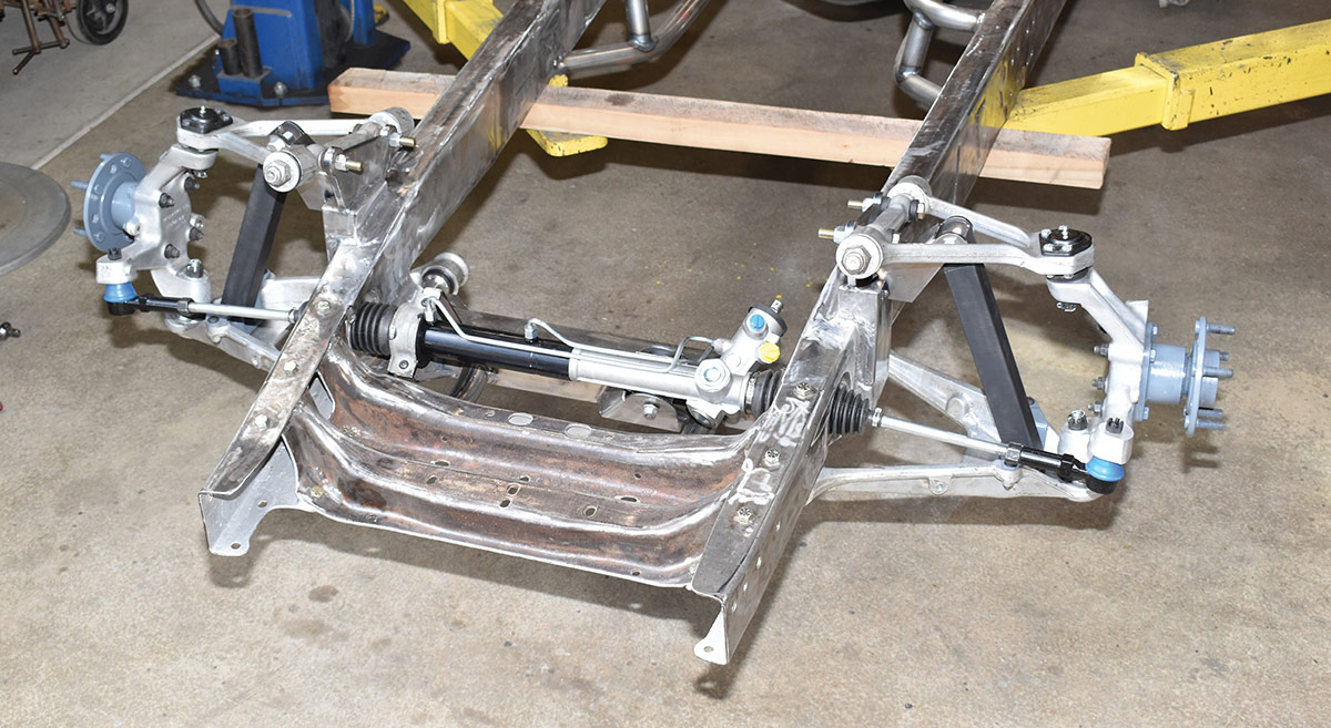
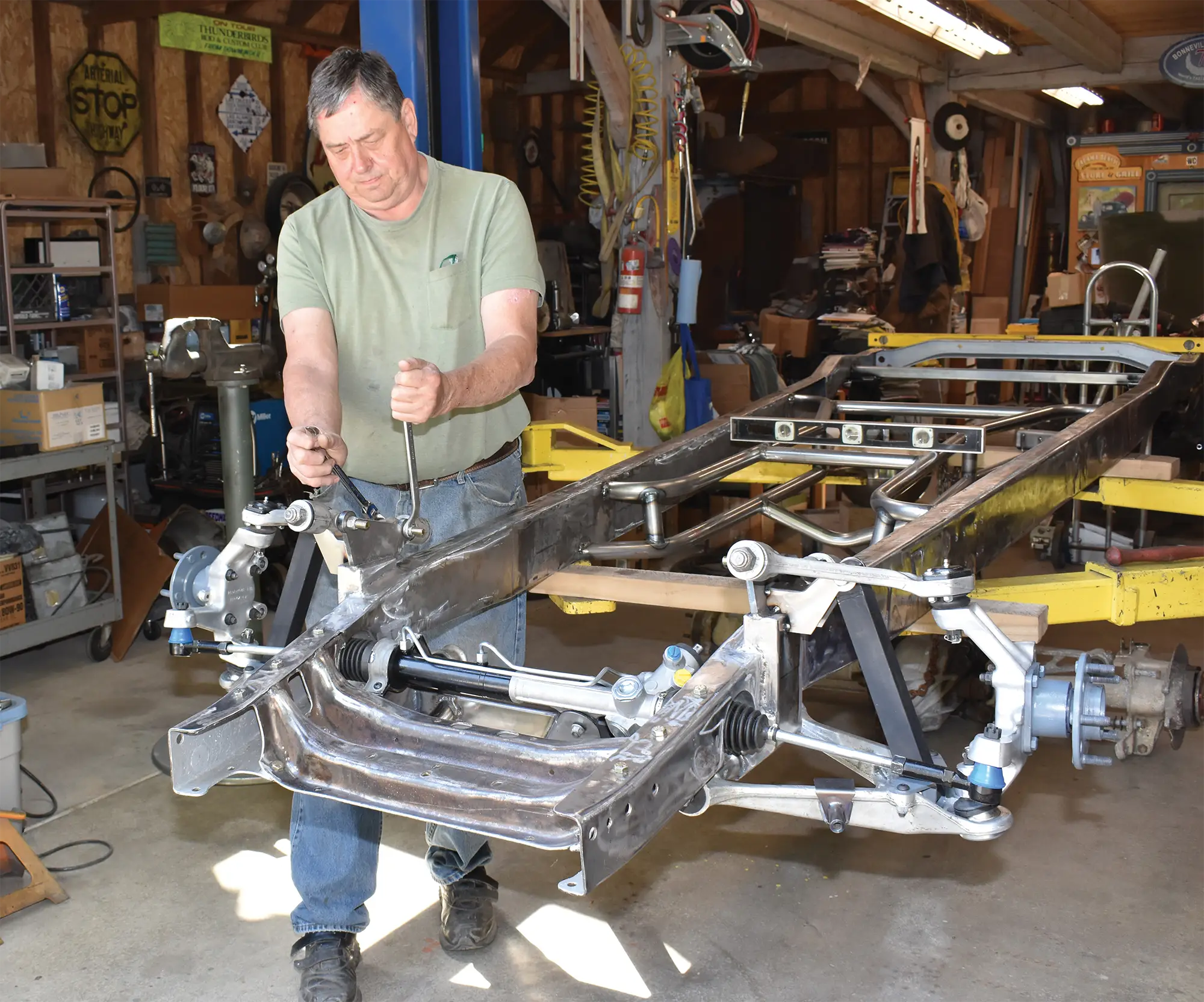
Paul Wilson finishes the preliminary installation of Flat Out Engineering’s Corvette C4 front suspension on his Chevy pickup’s frame. Yet to come are the brakes and the Aldan coilovers.
1. Paul Wilson finishes the preliminary installation of Flat Out Engineering’s Corvette C4 front suspension on his Chevy pickup’s frame. Yet to come are the brakes and the Aldan coilovers.
Independent Thinking
Part 2: C4 Corvette Suspension for Early Chevy
Pickups
BY Ron CeridonoPhotography BY THE AUTHOR
I

n the Aug. ’23 issue of Classic Truck Performance we began the installation of C4 Corvette front and rear suspension under Paul Wilson’s ’52 Chevy pickup with components from Don McNeil’s Flat Out Engineering. We planned on installing a small-block Chevy for power, and while there was a certain appeal to keeping our hauler all Bowtie from end to end, there was a more practical reason for Corvette suspension than brand loyalty. We knew the C4 suspension would provide excellent ride and handling characteristics and McNeil’s installation kits would make our truck’s transformation quick and easy. The one thing we didn’t anticipate was a problem with the factory frame.

McNeil has decades of experience building award-winning vehicles of all descriptions—drag racers, Bonneville competitors, show winners, and street machines. As an avid hot rodder and astute businessman, McNeil knows full well how important it is to establish the reputation for offering chassis parts that fit and work as intended, which he has done. He also knows that if you start off with a frame that is out of square the end result will be a chassis that will not work as it should. That’s why McNeil stresses that checking the frame for dimensional accuracy is the first step to installing his kits. In our case, the frame was out of square 5/16 inch, the max should be 1/8 inch. It took some effort, but with the frame square we installed the Flat Out Engineering front crossmember—which is where we left off last time.

With the crossmember in place the next steps were to notch the framerails to clear the rack-and-pinion steering, install the C-notch supports, and install the Flat Out Engineering boxing plates. The trick here is to make sure the framehorns, and as a result the front crossmember that mounts the core support, remain in the proper position relative to the tops of the framerails. In this case, Wilson elected to install a pair of tubing braces from the stock front crossmember to the Flat Out Engineering crossmember. They served to maintain the stock crossmember’s position while the C-notches were cut and add some support to it as well.

Once the front of the frame modifications were complete it was then time to turn our attention to the Corvette steering and suspension components. Wilson had come across a bargain on a complete ’86 Corvette as a parts donor, but despite the desirable components, like any car its age, time and mileage had taken their toll, so some replacement parts were needed. The power rack-and-pinion steering showed signs of leaking and one of the inner tie-rod ends was loose, so the entire assembly was replaced with a rebuild unit along with the outer tie-rod ends. Likewise, all the rubber control arm bushings were weathered and cracked so replacements from Prothane (available from Flat Out Engineering) were installed in the aluminum control arms. Finally, new ball joints were installed in the upper and lower control arms. One of the last steps to finishing the front suspension will be the installation of the sway bar, however, that will have to wait until the core support is in place to determine if the sway bar goes above or below the framerails.

Next time we’ll show how the C4 independent rear suspension is installed and how to properly assemble and adjust the Aldan coilovers.
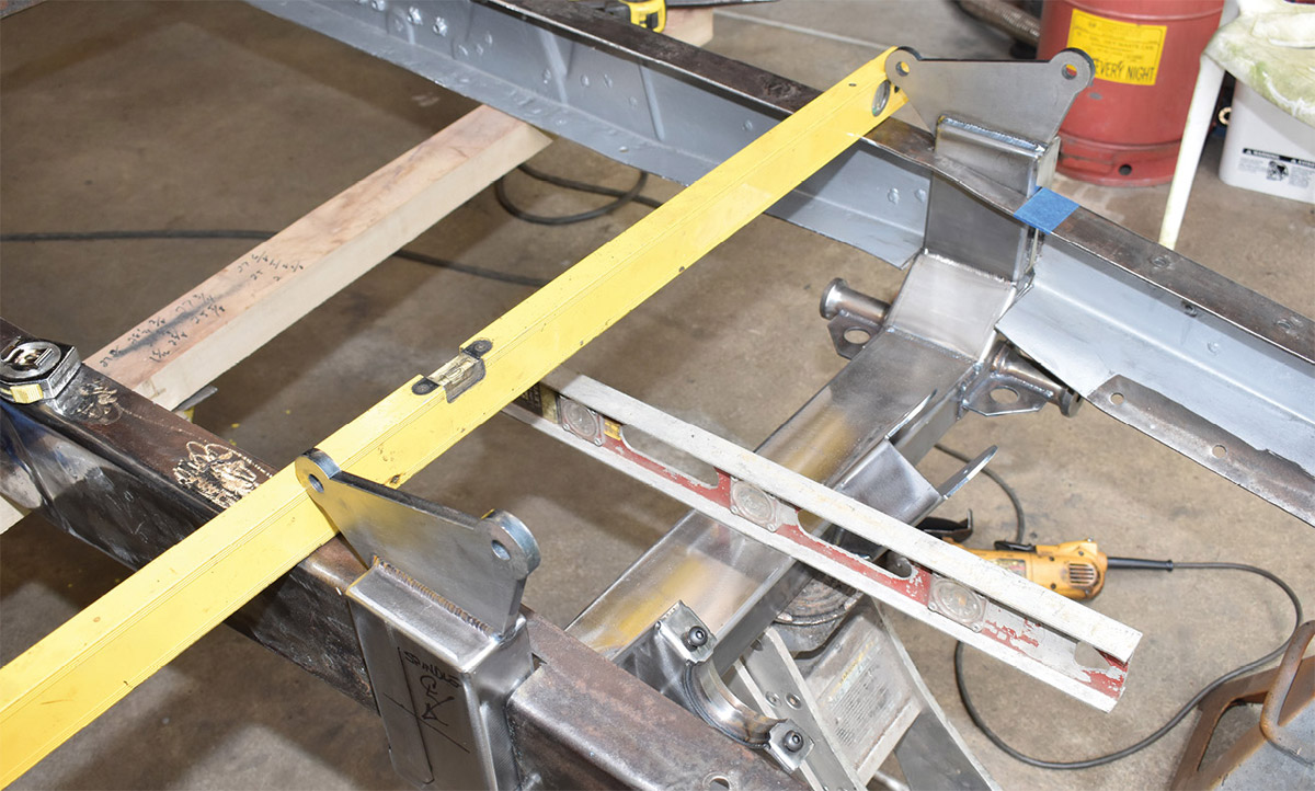
This is where we left off in our last installment: The frame was leveled side to side, set at a nose-down 2-degree rake, and the Flat Out Engineering crossmember was installed level with the ground.
2. This is where we left off in our last installment: The frame was leveled side to side, set at a nose-down 2-degree rake, and the Flat Out Engineering crossmember was installed level with the ground.
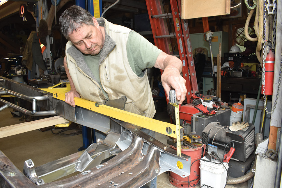
Prior to notching the frame for steering rack clearance, the “droop” of the front framerails was measured and recorded.
3. Prior to notching the frame for steering rack clearance, the “droop” of the front framerails was measured and recorded.
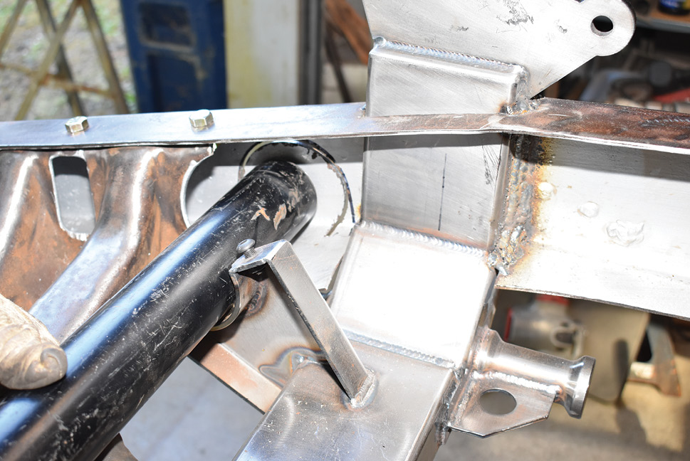
In addition to the measurements supplied by Flat Out Engineering, a piece of tubing was used to simulate the location of the steering rack and verify the location of the C-notch.
4. In addition to the measurements supplied by Flat Out Engineering, a piece of tubing was used to simulate the location of the steering rack and verify the location of the C-notch.
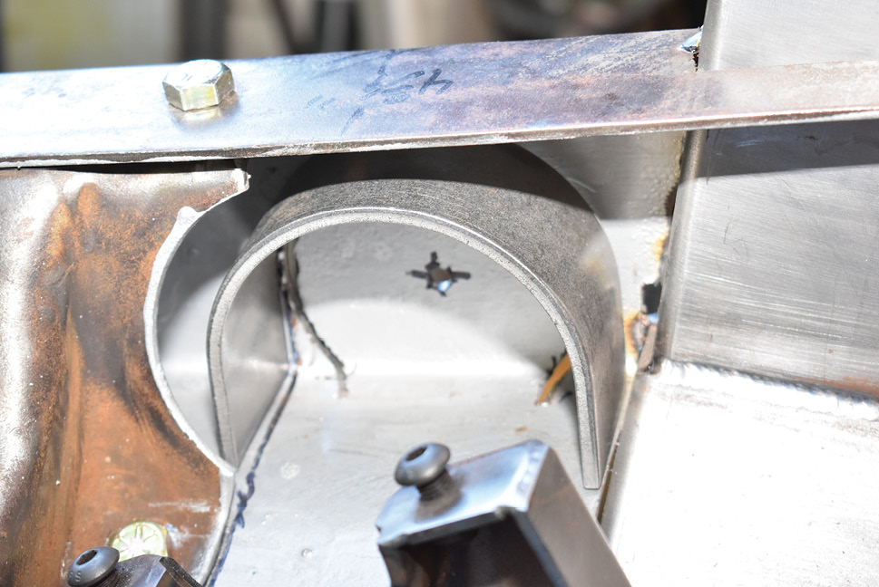
The U-shaped C-notch reinforcement is part of the Flat Out Engineering kit. After marking the center of the cuts to be made for the notches, pilot holes were drilled in the framerails.
5. The U-shaped C-notch reinforcement is part of the Flat Out Engineering kit. After marking the center of the cuts to be made for the notches, pilot holes were drilled in the framerails.
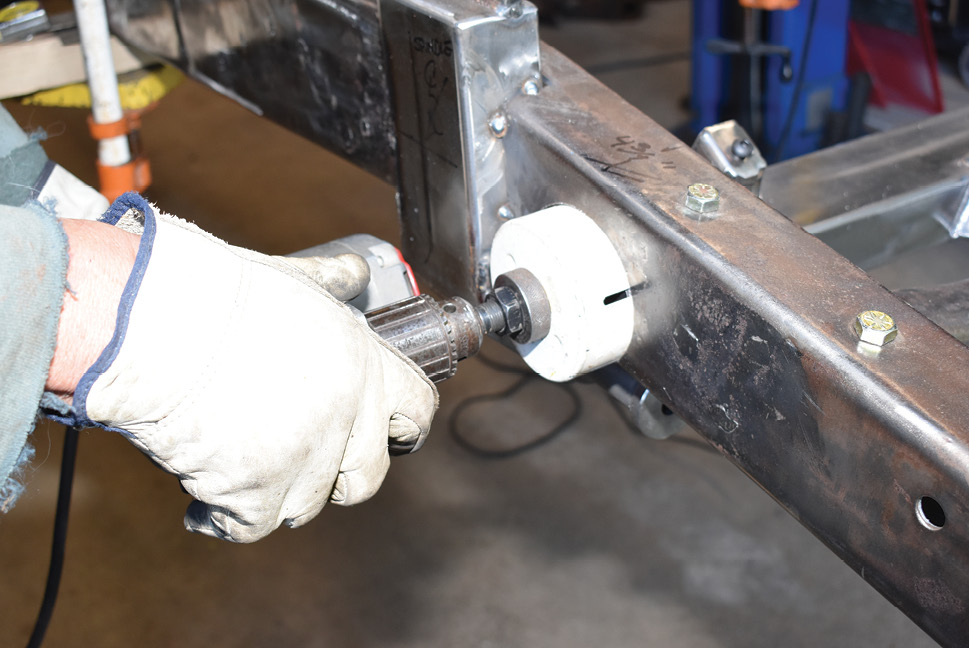
By registering in the pilot holes, a hole saw was used to make the initial cuts in the framerails—an abrasive wheel was used to trim the holes and make them an inverted C-notch.
6. By registering in the pilot holes, a hole saw was used to make the initial cuts in the framerails—an abrasive wheel was used to trim the holes and make them an inverted C-notch.
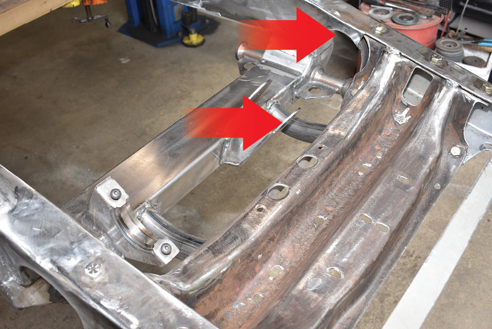
Here the notches have had the C-notches filled in and the front Flat Out Engineering boxing plates have been added, as can be seen on the left framerail (<i>top arrow</i>).  Note the added reinforcements (<i>bottom arrow</i>) to support the front crossmember.
7. Here the notches have had the C-notches filled in and the front Flat Out Engineering boxing plates have been added, as can be seen on the left framerail (top arrow). Note the added reinforcements (bottom arrow) to support the front crossmember.
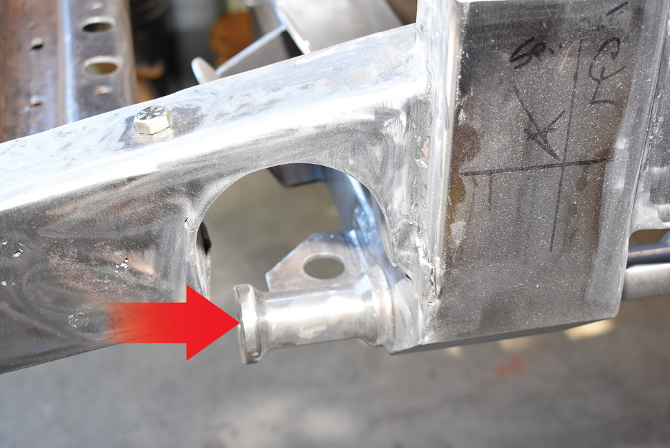
This is the finished C-notch in the left framerail from the outside. The lower control arm mount (arrow) isn’t as close to the bottom of the C-notch as it appeared.
8. This is the finished C-notch in the left framerail from the outside. The lower control arm mount (arrow) isn’t as close to the bottom of the C-notch as it appeared.
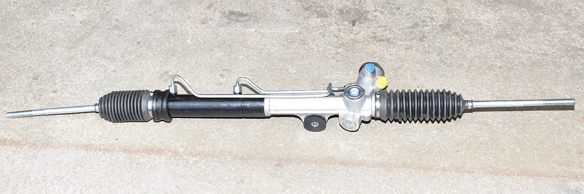
Our ’86 Corvette donor car had some miles on it. As a result, we replaced the rack-and-pinion with a rebuilt unit; they’re available from Flat Out Engineering.
9. Our ’86 Corvette donor car had some miles on it. As a result, we replaced the rack-and-pinion with a rebuilt unit; they’re available from Flat Out Engineering.
The rack-and-pinion unit bolts into the bracket on the new crossmember on the driver side and uses the original Corvette retainer on the right to hold it in place.
10. The rack-and-pinion unit bolts into the bracket on the new crossmember on the driver side and uses the original Corvette retainer on the right to hold it in place.
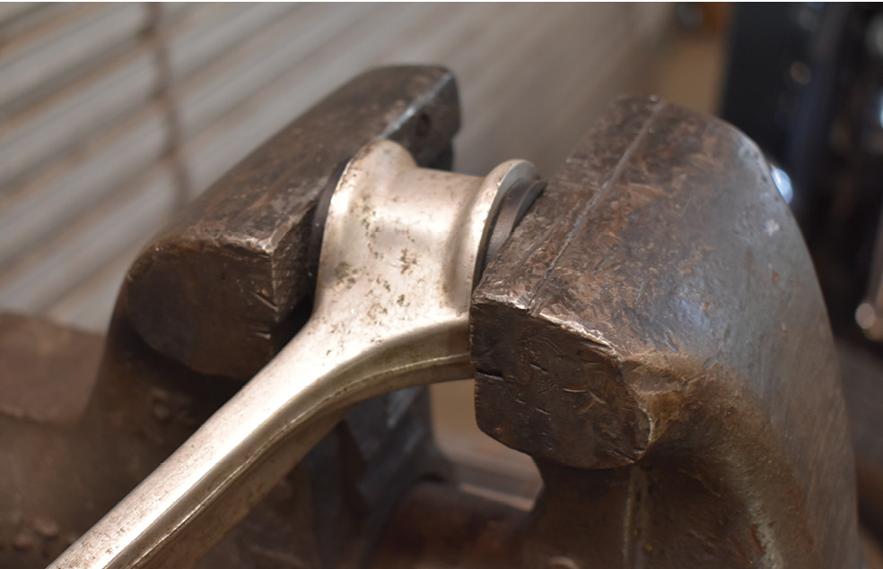
To freshen the C4 suspension all the control arm bushings were replaced. The lowers were pressed in place with a vise.
11. To freshen the C4 suspension all the control arm bushings were replaced. The lowers were pressed in place with a vise.
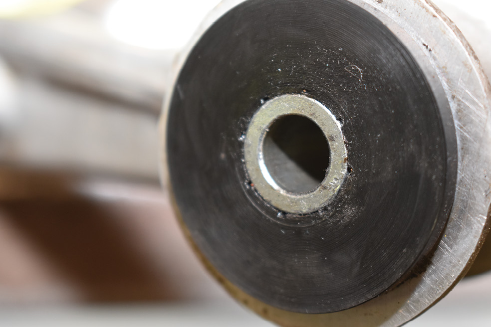
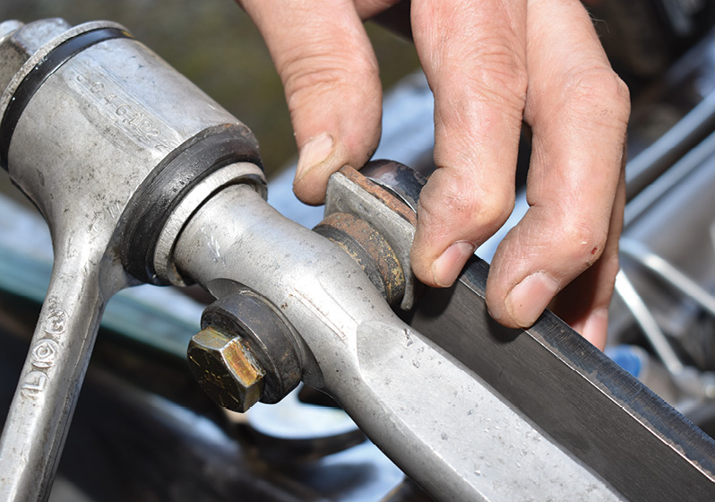
The new polyurethane bushings rotate on the steel inner sleeve. Tiny grooves in the bushings are filled with lubricant before assembly.
12. The new polyurethane bushings rotate on the steel inner sleeve. Tiny grooves in the bushings are filled with lubricant before assembly.
Included in the Flat Out Engineering kit are two long shafts that hold the lower control arms in place.
13. Included in the Flat Out Engineering kit are two long shafts that hold the lower control arms in place.
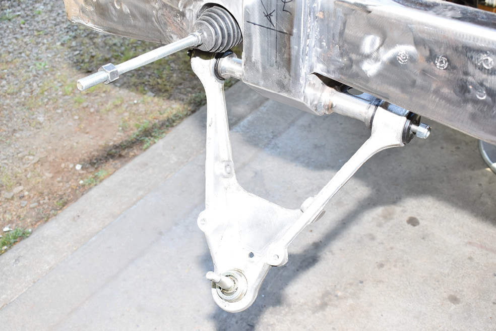
Here the aluminum C4 lower control arms are installed—be aware there are left- and right-side control arms.
14. Here the aluminum C4 lower control arms are installed—be aware there are left- and right-side control arms.
While the suspension was apart we elected to install new ball joints. The originals are riveted in place.
15. While the suspension was apart we elected to install new ball joints. The originals are riveted in place.
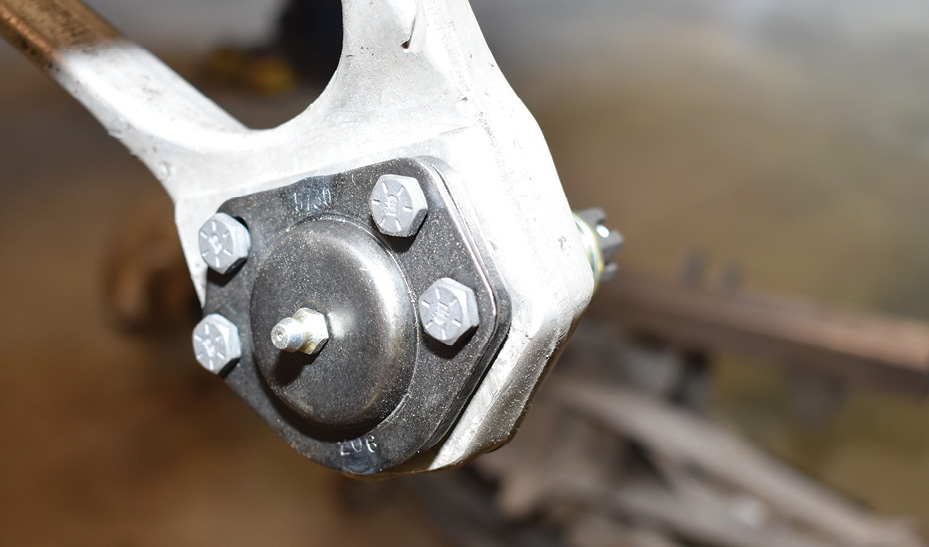
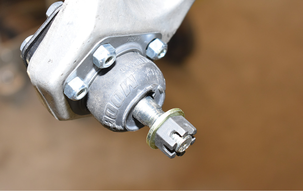
The new MOOG ball joints are held in place by the supplied Grade 8 capscrews and lock nuts.
16. The new MOOG ball joints are held in place by the supplied Grade 8 capscrews and lock nuts.
This is one of the eight concave washers that are used with the Corvette’s upper control arm cross shafts.
17. This is one of the eight concave washers that are used with the Corvette’s upper control arm cross shafts.
The concave portion of the washers fit against the raised convex areas around the cross shaft attachment holes.
18. The concave portion of the washers fit against the raised convex areas around the cross shaft attachment holes.
Aligning the front suspension is done with shims between the upper control arm cross shaft and the mount on the Flat Out Engineering crossmember.
19. Aligning the front suspension is done with shims between the upper control arm cross shaft and the mount on the Flat Out Engineering crossmember.
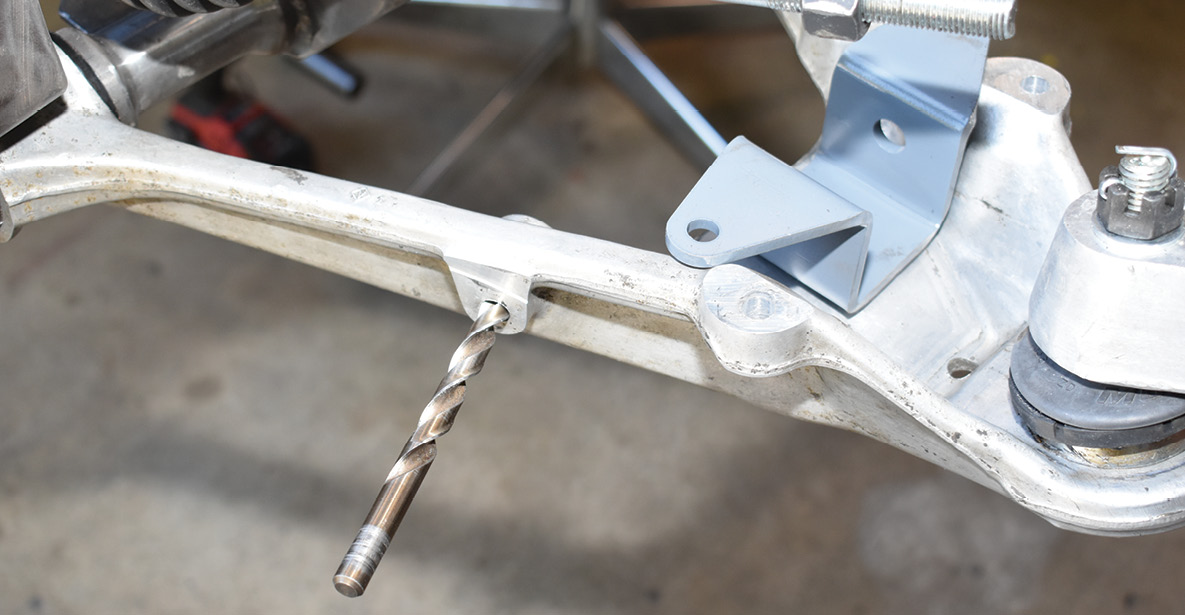
The lower coilover shock mount attaches to the lower control arms after the holes are drilled to 3/8 inch.
20. The lower coilover shock mount attaches to the lower control arms after the holes are drilled to 3/8 inch.
Here the lower brackets have been attached to the control arm with the provided hardware. When the Aldan coilovers are installed they will be attached to the bracket then the assembly will be installed as a unit.
21. Here the lower brackets have been attached to the control arm with the provided hardware. When the Aldan coilovers are installed they will be attached to the bracket then the assembly will be installed as a unit.
The optional Flat Out Engineering sway bar bracket attaches to the factory hole in the front of the control arms after they are drilled to 3/8 inch.
22. The optional Flat Out Engineering sway bar bracket attaches to the factory hole in the front of the control arms after they are drilled to 3/8 inch.
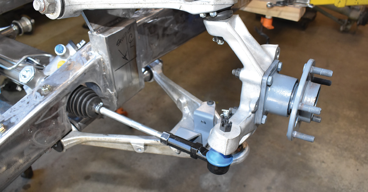
With the control arms in place the C4 aluminum uprights and cartridge spindles were installed. While we were replacing parts we opted for new outer tie-rod ends.
23. With the control arms in place the C4 aluminum uprights and cartridge spindles were installed. While we were replacing parts we opted for new outer tie-rod ends.
The completed installation is not only clean looking but will provide the smooth ride and outstanding handling these suspensions are known for. Note the temporary struts that hold the suspension at ride height.
24. The completed installation is not only clean looking but will provide the smooth ride and outstanding handling these suspensions are known for. Note the temporary struts that hold the suspension at ride height.
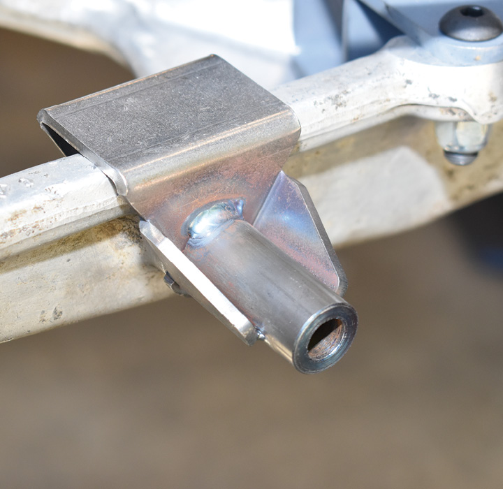
This is one of the Flat Out Engineering sway bar brackets that attach to the lower control arms.
25. This is one of the Flat Out Engineering sway bar brackets that attach to the lower control arms.
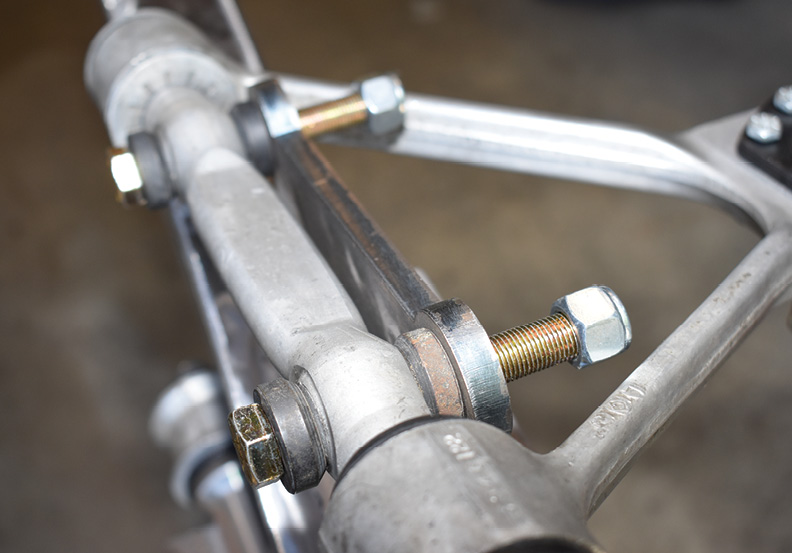
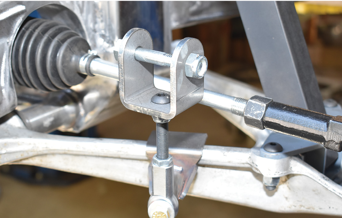
Adjustable links bolt to the control arm brackets to allow the stock Corvette sway bar to be mounted above or below the framerails.
26. Adjustable links bolt to the control arm brackets to allow the stock Corvette sway bar to be mounted above or below the framerails.
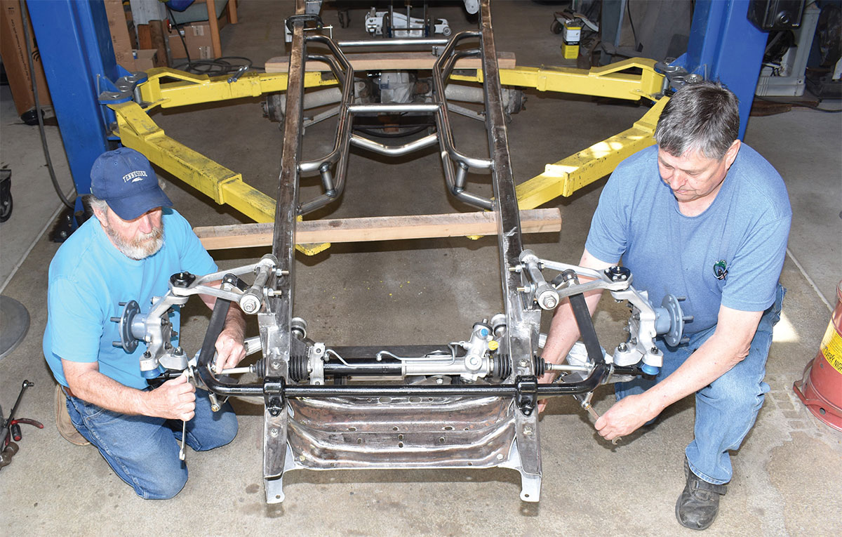
Paul Willis (left) and Wilson mock up mounting the sway bar above the framerails. Its final position will be determined when the radiator core support is in place.
27. Paul Willis (left) and Wilson mock up mounting the sway bar above the framerails. Its final position will be determined when the radiator core support is in place.
 SOURCES
ALDAN AMERICAN
(310) 834-7478
aldanamerican.com
FLAT OUT ENGINEERING
(714) 639-2623
flatout-engineering.com
PROTHANE SUSPENSION PARTS
(888) 406-2330
prothanesuspensionparts.com