CTP Tech
InTheGarageMedia.com
Every project starts somewhere. It took a long search to find a weathered but basically sound truck to start with.
1. Every project starts somewhere. It took a long search to find a weathered but basically sound truck to start with.
HOLM BUILT
Holm Built Hotrods’ “Trans-Am” Bumpside Build
BY Ron Covell
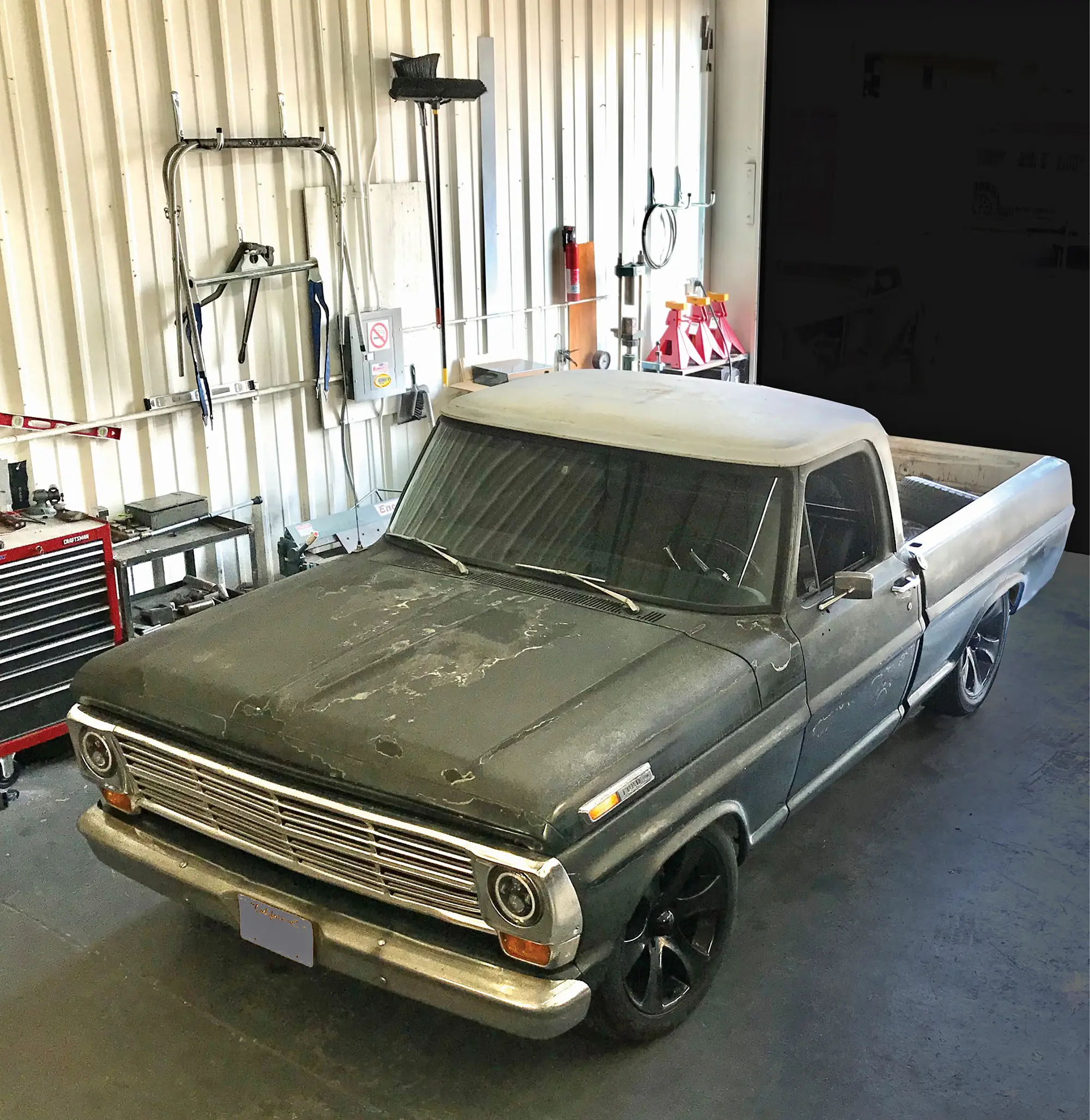
Photography BY THE AUTHOR
I

n the mid ’60s a new class for racing cars was launched. These were based on production sedans, which were extensively reworked to make them competitive for circuit racing. The cars were fitted with full rollcages, state-of-the-art suspension and brakes, and powerful but reliable engines. That was the beginning of the Trans-Am series, which continues to this day.

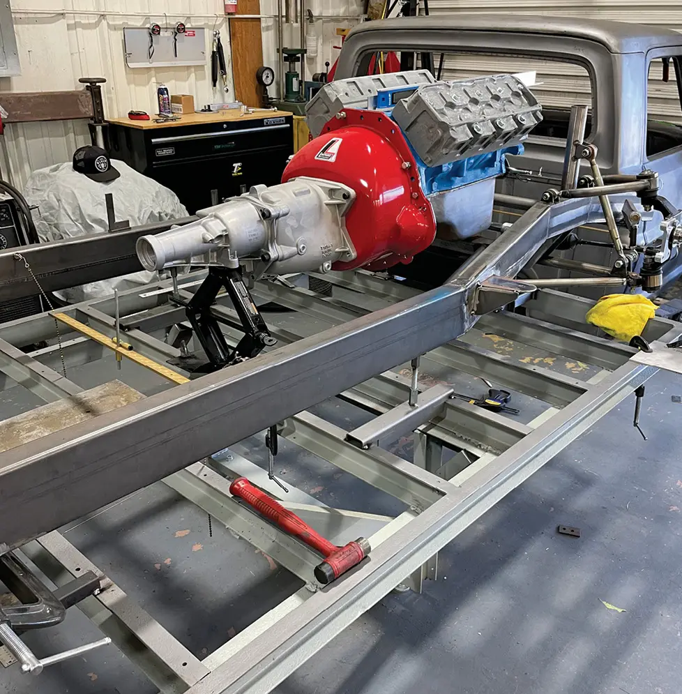
Casey Holm, of Holm Built Hot Rods in Northern California, has always been fascinated by the purpose-built design used in this class of racing. Shawn Arnold, a longtime friend and customer of Holm, wanted to build a new, truck-based project that was aligned with the Trans-Am theme. Arnold found a Boss 302 engine at TOE Racing Engines and had them build a street-friendly engine in the Trans-Am style using a number of rare, period-correct components. The plan for the build was to keep the same attention to detail and focus on the performance that was used in the Trans-Am series.

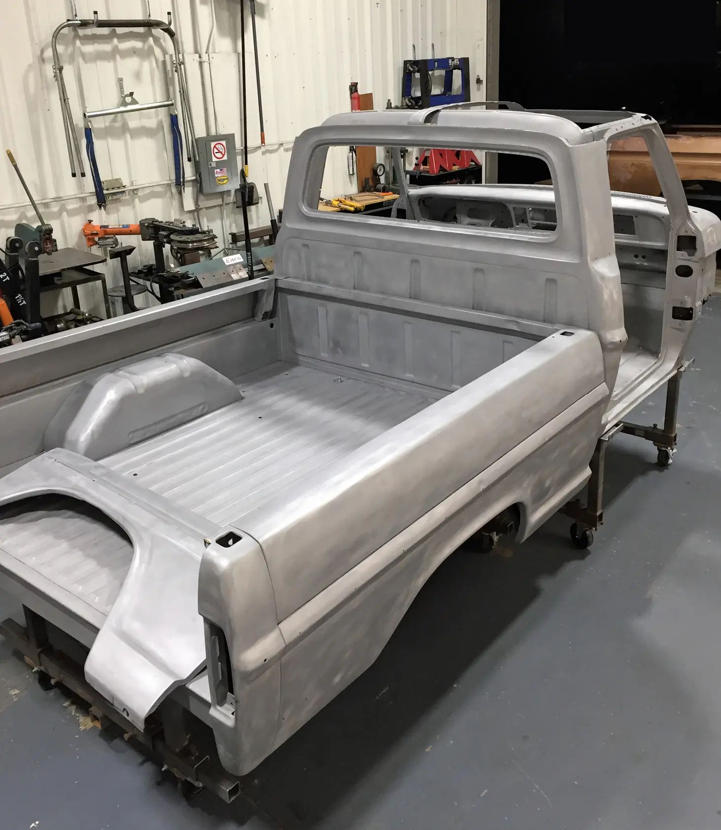
It took an extensive search to find a good truck to start with. Most 50-year-old commercial vehicles get pretty battered, and rust often takes a toll on metal that old. The search finally paid off and they found a solid candidate with minimal rust and only minor body damage. After disassembly, all the body panels were stripped by media blasting.

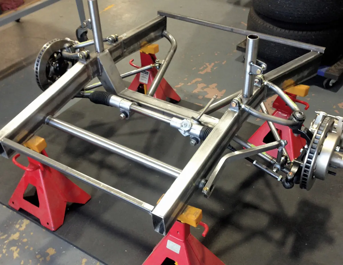
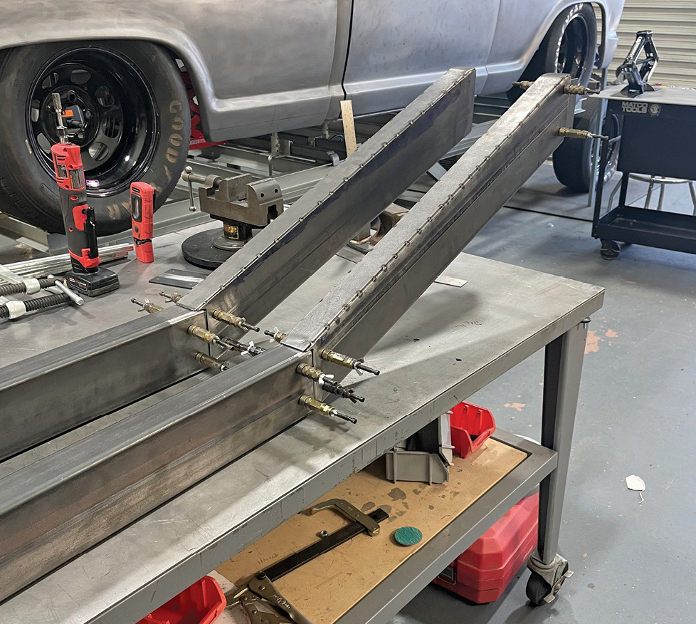
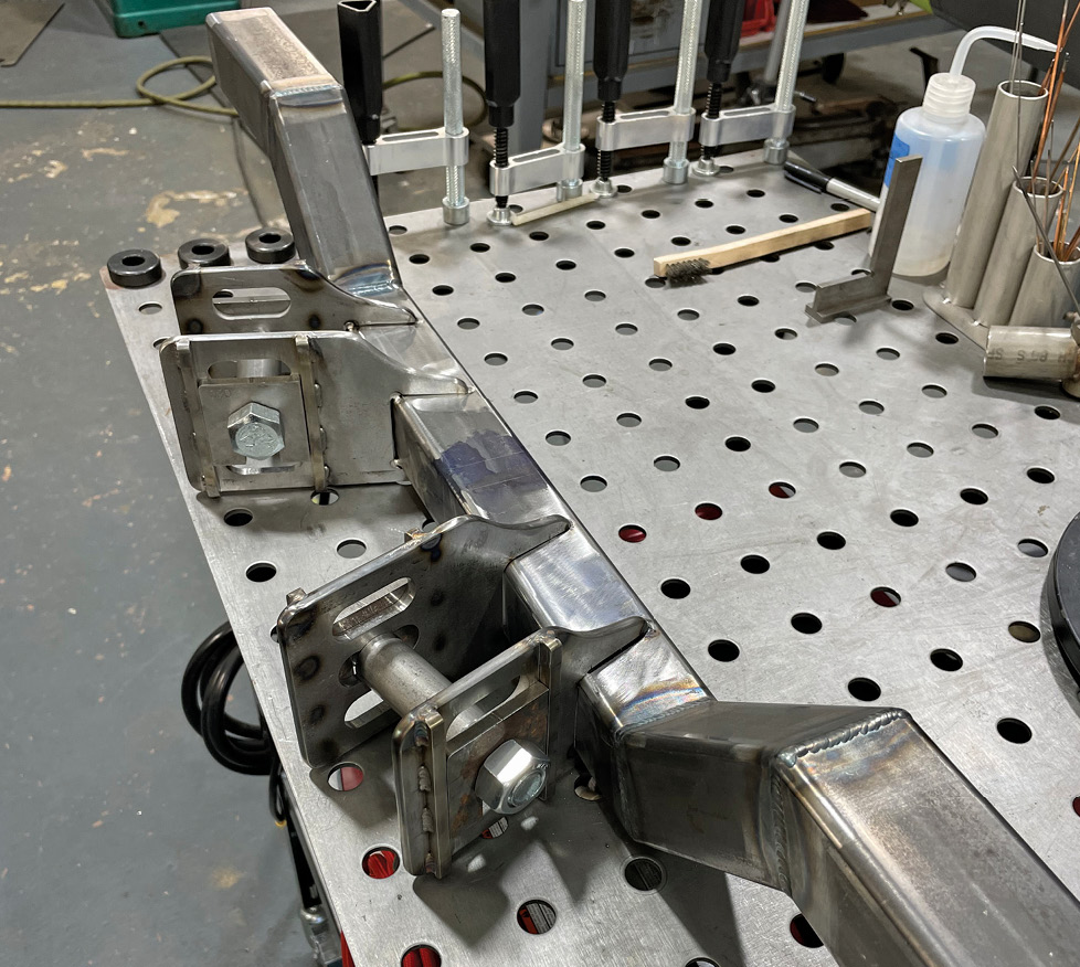
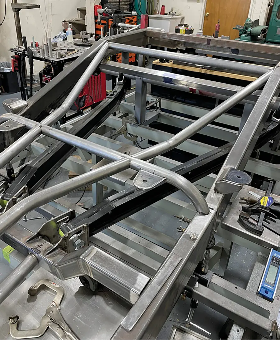
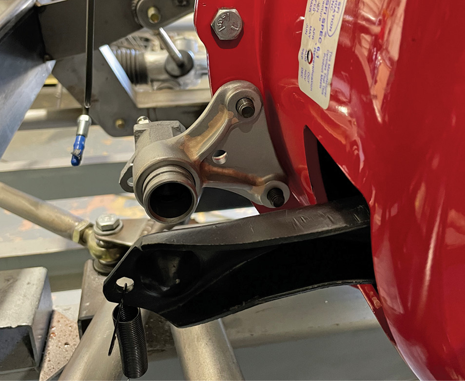
The plan included a new chassis that incorporated a high-performance drivetrain. A top priority was replacing the old twin I-beam front suspension with a race-tuned double-wishbone design. Penske Racing coilover shocks will be used front and rear, along with beefy antiroll bars.

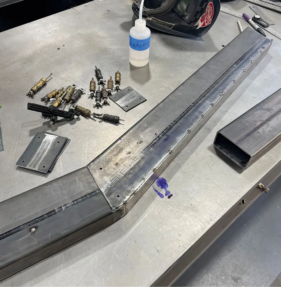
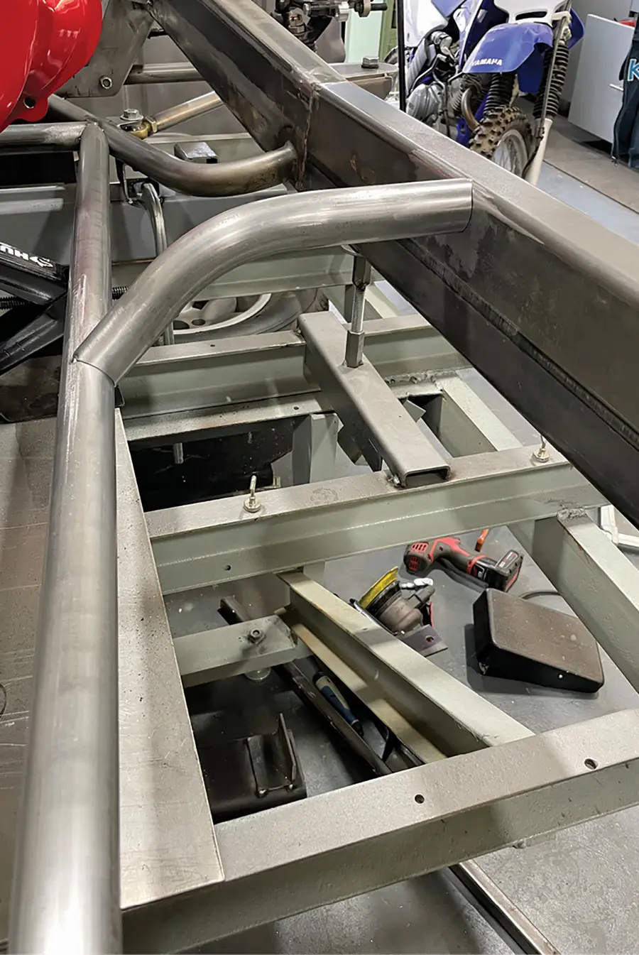
There were a lot of factors to consider when designing the new chassis, such as tweaking the wheelbase, establishing the proper ride height, building in robust torsional stiffness, and allowing adequate room for wide tires and a large, free-flowing exhaust system that will exit through the bedsides. They started by purchasing a front suspension clip from RPM Classics in Ontario, Canada—designed for racing but robust enough for street use.

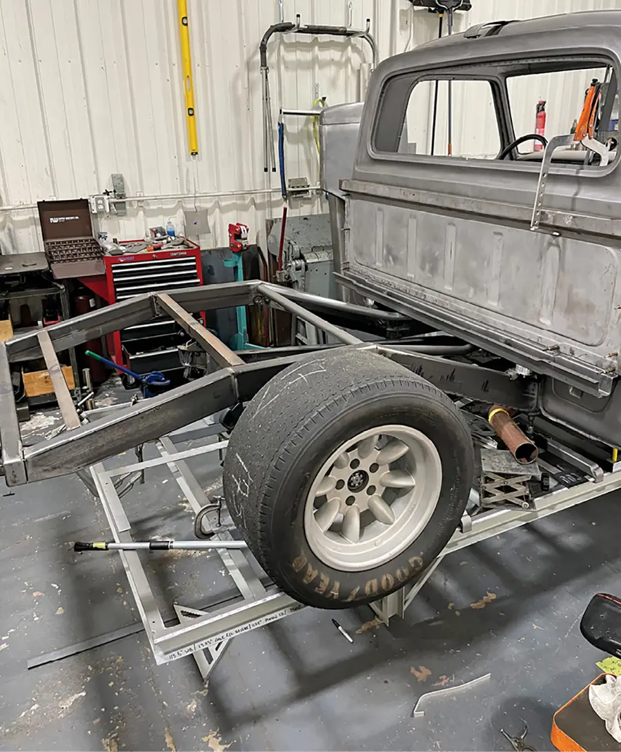
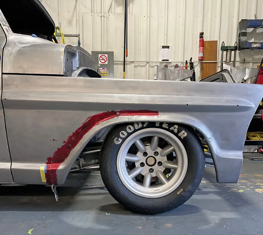
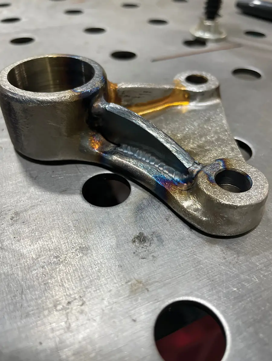
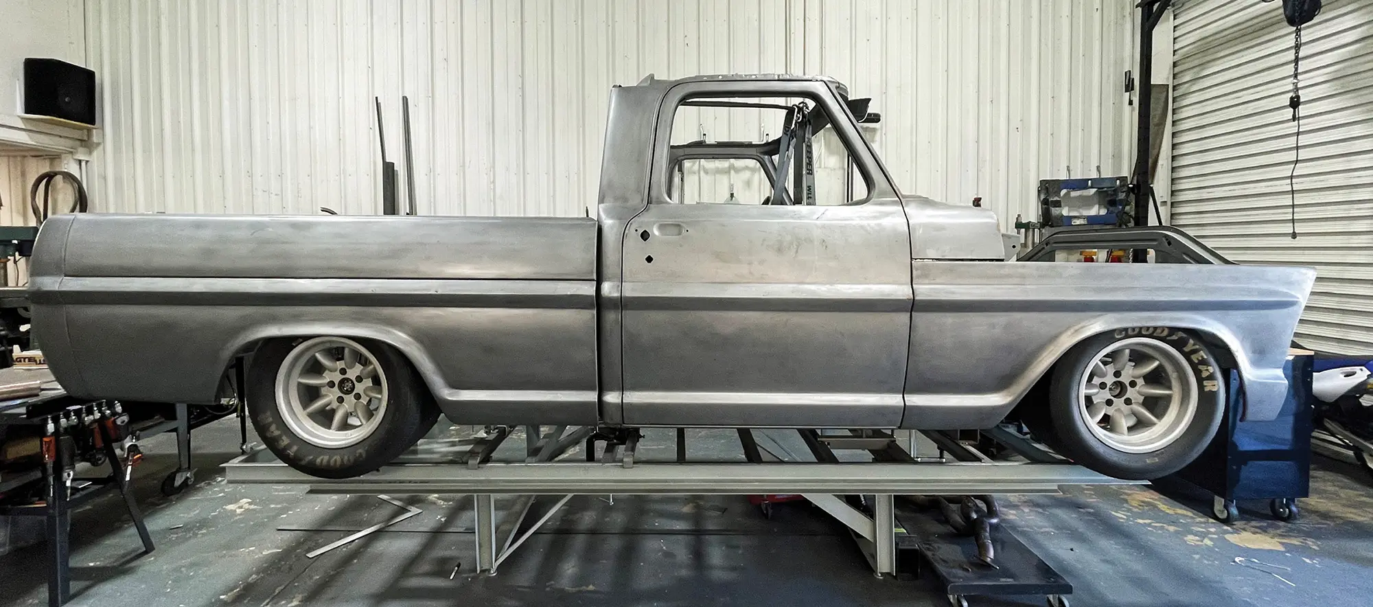
With the front clip as a starting point, the chassis was mocked up with the era-correct wheels and tires, 600-15s in front and 800-15s in the rear. TBM Brakes were selected and special brackets were needed to fit them inside the 15-inch wheels in the Trans-Am style.

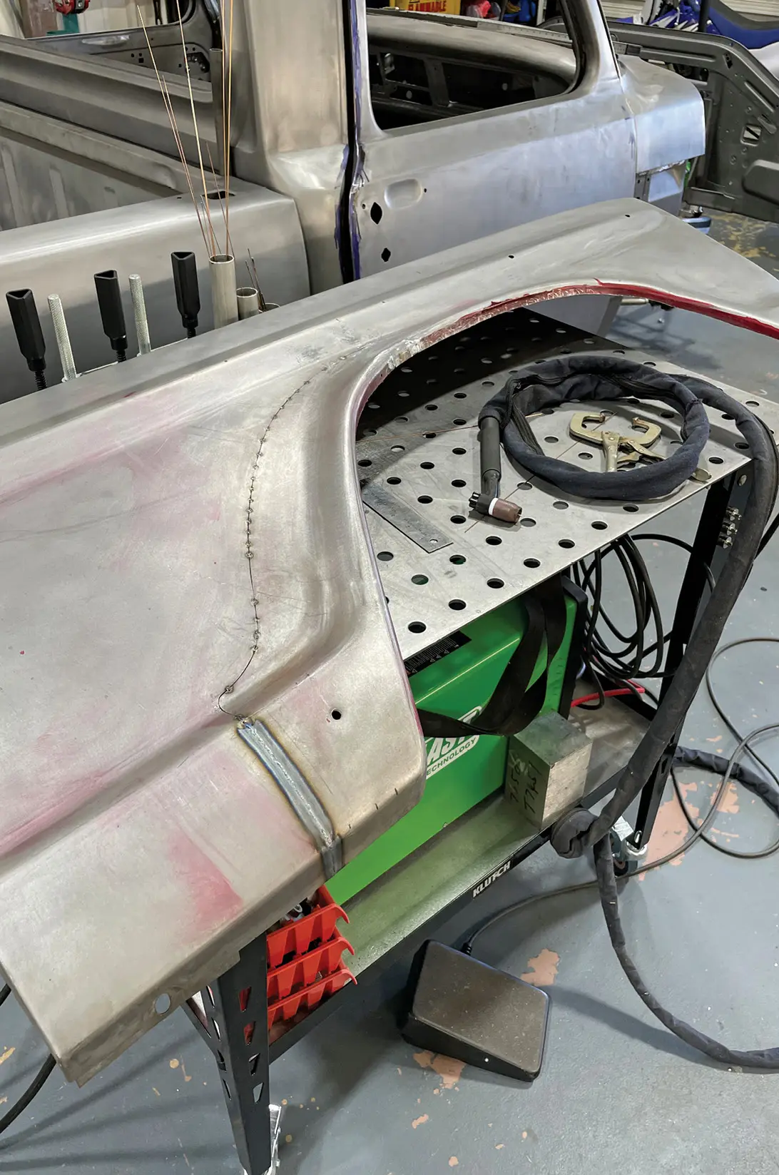
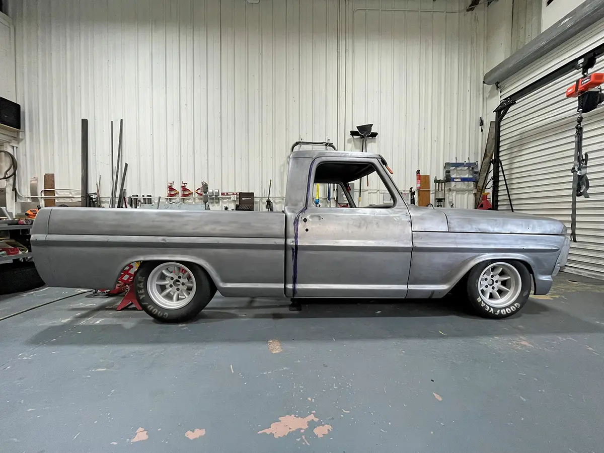
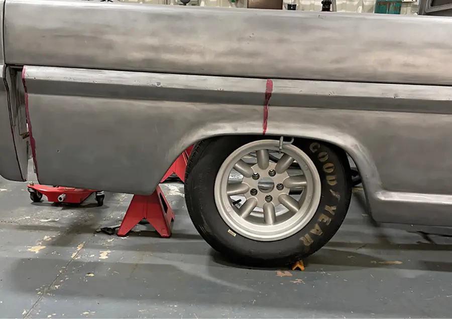
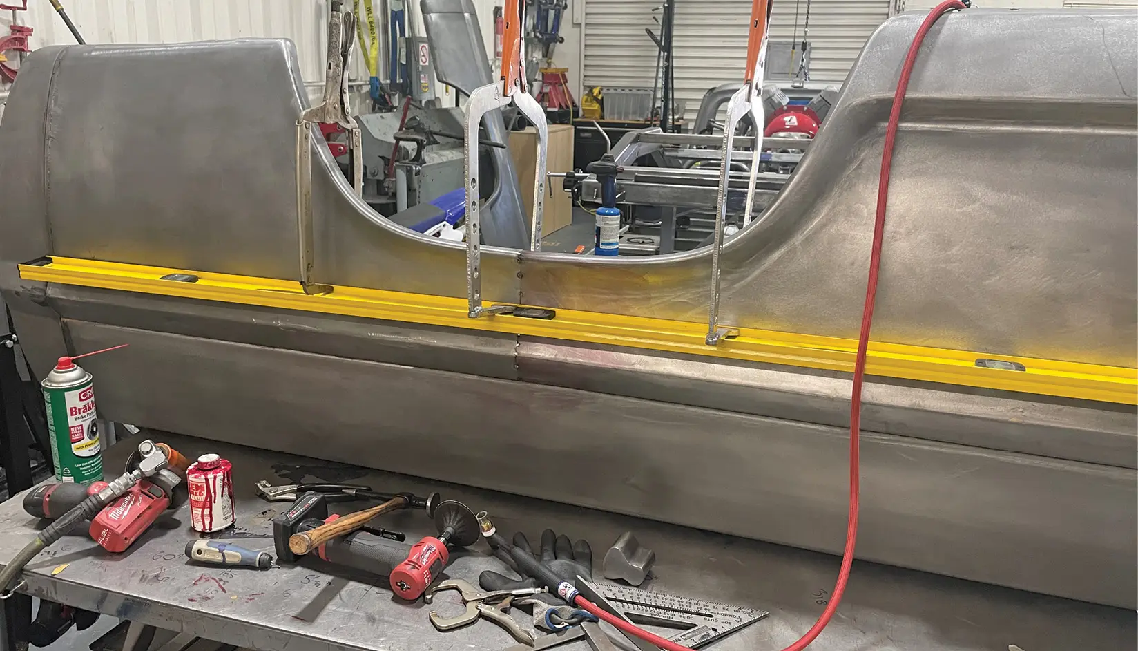
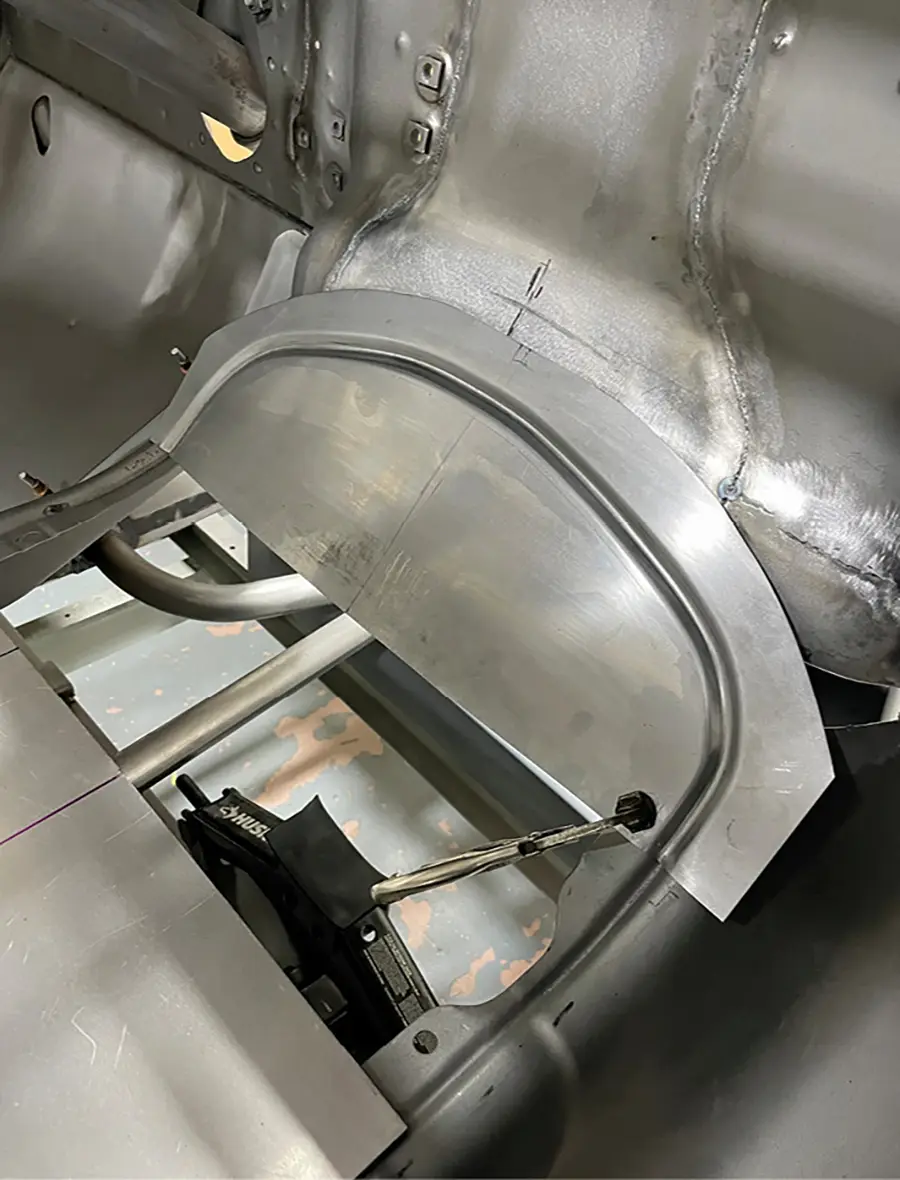
It quickly became apparent that the wheel openings in the front fenders were too large, so Holm moved the front fenders and cab reward 1-1/2 inches and moved the rear portion of the front fender forward 2-1/2 inches. This gave the perfect look at the front of the truck, and the bed was next. The bed was moved forward a 1/2 inch to reduce the gap at the cab. The bottom rear portion of the bed was moved forward 2-1/2 inches and the rear of the bed was shortened 1 inch. The rear axle was positioned so the wheels were centered in the openings, which resulted in the wheelbase being shortened 2 inches. The ride height was established so the wheels were shrouded just the right amount, and the width of the rear axle was calculated to give the tires adequate clearance with the bed. These subtle changes were essential to give the truck the purpose-built look of the Trans-Am cars of the era.

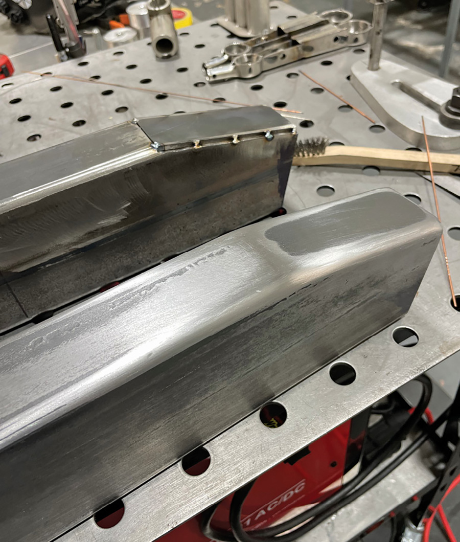
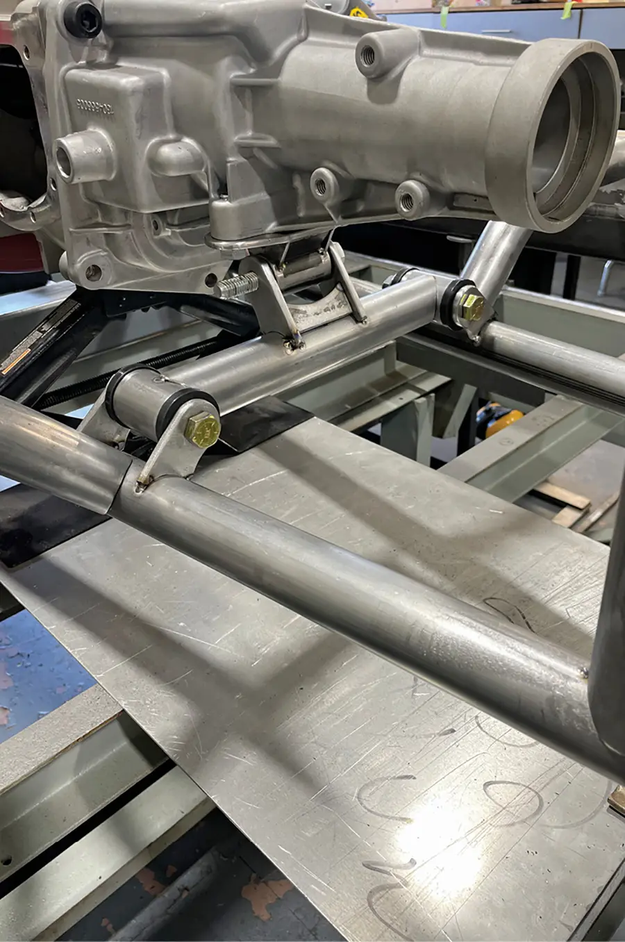
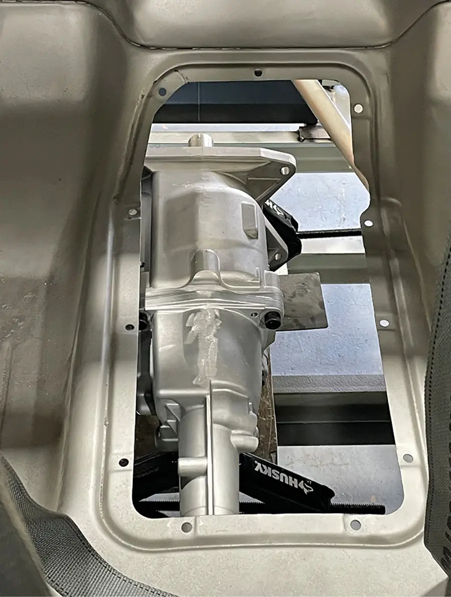
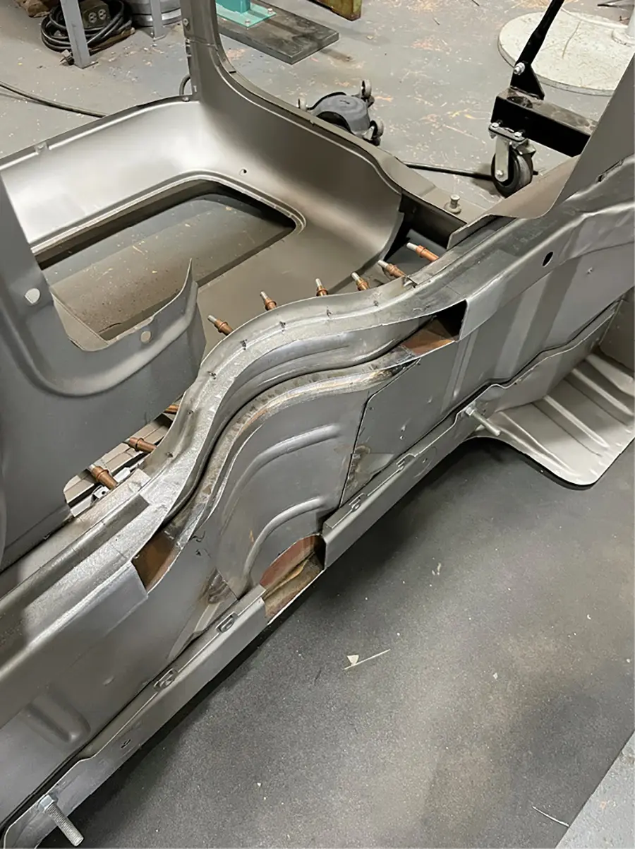
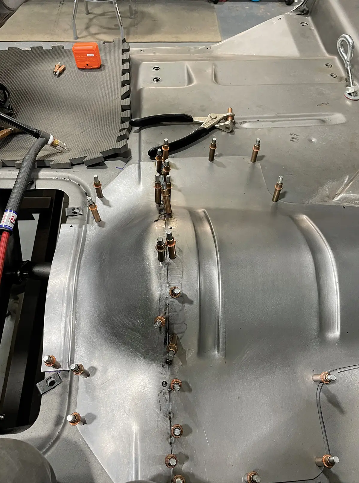
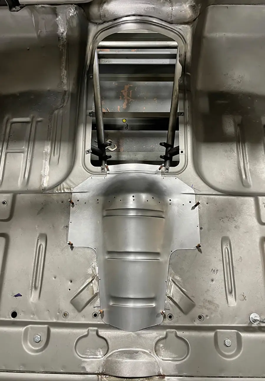
The engine was moved back as much as possible, which required extensive modifications to the firewall and transmission cover. This work was beautifully executed to have an OEM look—no hack and patch job here.

As with any major project like this, the devil is in the details, and the photos give you a taste of some of the intense work that has been lavished on the truck so far. This will truly be a one-of-a-kind project when it’s finished!

One of the first steps was to disassemble the truck and media blast all the panels. The roofskin required replacement, so it was removed before blasting to facilitate cleaning the inner structure.
2. One of the first steps was to disassemble the truck and media blast all the panels. The roofskin required replacement, so it was removed before blasting to facilitate cleaning the inner structure.
This unequal-length A-arm independent suspension clip from RPM Classics was the start of the custom-built chassis. Brakes are from TBM and Penske coilovers will be fitted.
3. This unequal-length A-arm independent suspension clip from RPM Classics was the start of the custom-built chassis. Brakes are from TBM and Penske coilovers will be fitted.
With the engine and front clip mocked up on the chassis table, the main framerails were positioned. The engine was moved back as much as possible without reducing legroom.
4. With the engine and front clip mocked up on the chassis table, the main framerails were positioned. The engine was moved back as much as possible without reducing legroom.
Some of the chassis members were gently tapered. This removes some weight, adds space for other components, and gives the project a graceful, elegant look.
5. Some of the chassis members were gently tapered. This removes some weight, adds space for other components, and gives the project a graceful, elegant look.
Here the kick-up for the rear of the frame is mocked up on the bench. Great care was taken to make everything symmetrical.
6. Here the kick-up for the rear of the frame is mocked up on the bench. Great care was taken to make everything symmetrical.
This beefy crossmember is for the heavy-duty aftermarket “Truck Arm” axle locating members. Note the adjustability for the height of the pivots—taking a page from race car suspension tuning.
7. This beefy crossmember is for the heavy-duty aftermarket “Truck Arm” axle locating members. Note the adjustability for the height of the pivots—taking a page from race car suspension tuning.
The rear tips of the frame were tapered slightly to flow in with the rear crossmember.
8. The rear tips of the frame were tapered slightly to flow in with the rear crossmember.
Here is the rear portion of the frame, with the cab location mocked up. There is a straight shot for the exhaust system to run beneath the framerail, headed toward its exit on the side of the bed.
9. Here is the rear portion of the frame, with the cab location mocked up. There is a straight shot for the exhaust system to run beneath the framerail, headed toward its exit on the side of the bed.
The round tubing chassis members are being fitted to the framerails.
10. The round tubing chassis members are being fitted to the framerails.
These round chassis braces are bent to provide clearance for the exhaust system.
11. These round chassis braces are bent to provide clearance for the exhaust system.
A special, easy-to-remove transmission crossmember is being fitted to the X-member. The transmission is a Super T10 aluminum four-speed.
12. A special, easy-to-remove transmission crossmember is being fitted to the X-member. The transmission is a Super T10 aluminum four-speed.
The cab and front fender was moved rearward 1-1/2 inches to close the gap at the front of the wheel opening. The huge gap at the rear will be addressed next.
13. The cab and front fender was moved rearward 1-1/2 inches to close the gap at the front of the wheel opening. The huge gap at the rear will be addressed next.
Here you can see the filler piece being tack welded to the rear portion of the front fender to fit the wheel properly.
14. Here you can see the filler piece being tack welded to the rear portion of the front fender to fit the wheel properly.
With the front wheel opening dialed in, it’s time to address the rear, which obviously has some issues.
15. With the front wheel opening dialed in, it’s time to address the rear, which obviously has some issues.
Here some of the cuts are laid out on the bed. It will be shortened 3-1/2 inches.
16. Here some of the cuts are laid out on the bed. It will be shortened 3-1/2 inches.
After cutting and fitting, the bed sections are clamped together with a rigid straightedge as they are tack-welded back together.
17. After cutting and fitting, the bed sections are clamped together with a rigid straightedge as they are tack-welded back together.
For some reason, Ford placed the transmission cover way off-center. Holm went to a lot of trouble to make this area symmetrical and to allow room for the scattershield.
18. For some reason, Ford placed the transmission cover way off-center. Holm went to a lot of trouble to make this area symmetrical and to allow room for the scattershield.
The cab crossmembers were completely reworked to make them symmetrical.
19. The cab crossmembers were completely reworked to make them symmetrical.
Here’s the new transmission cover in-process.
20. Here’s the new transmission cover in-process.
A little farther along, some of the rear floor pieces are being fitted together.
21. A little farther along, some of the rear floor pieces are being fitted together.
After the work on the floor was completed, it looks like it was designed that way from the factory.
22. After the work on the floor was completed, it looks like it was designed that way from the factory.
A lot of work went into even the smallest details. This is a handcrafted mount for a new clutch slave cylinder. When finished, it will look like a forging.
23. A lot of work went into even the smallest details. This is a handcrafted mount for a new clutch slave cylinder. When finished, it will look like a forging.
Here’s the slave cylinder in place mounted to the bellhousing.
24. Here’s the slave cylinder in place mounted to the bellhousing.
This is how the truck project currently stands. The basic look and proportions are spot-on, and there is a lot of work left to do!
25. This is how the truck project currently stands. The basic look and proportions are spot-on, and there is a lot of work left to do!
 SOURCE
Holm Built Hot Rods
(831) 566-9594
@holmbuilt_hotrods