Tech
InTheGarageMedia.com

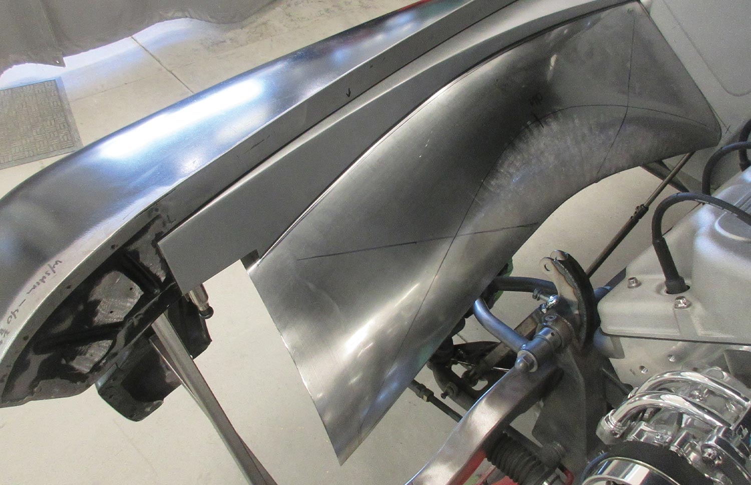
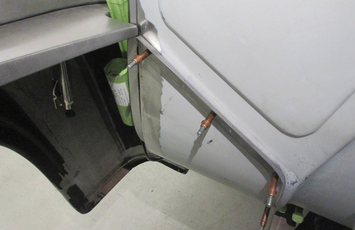
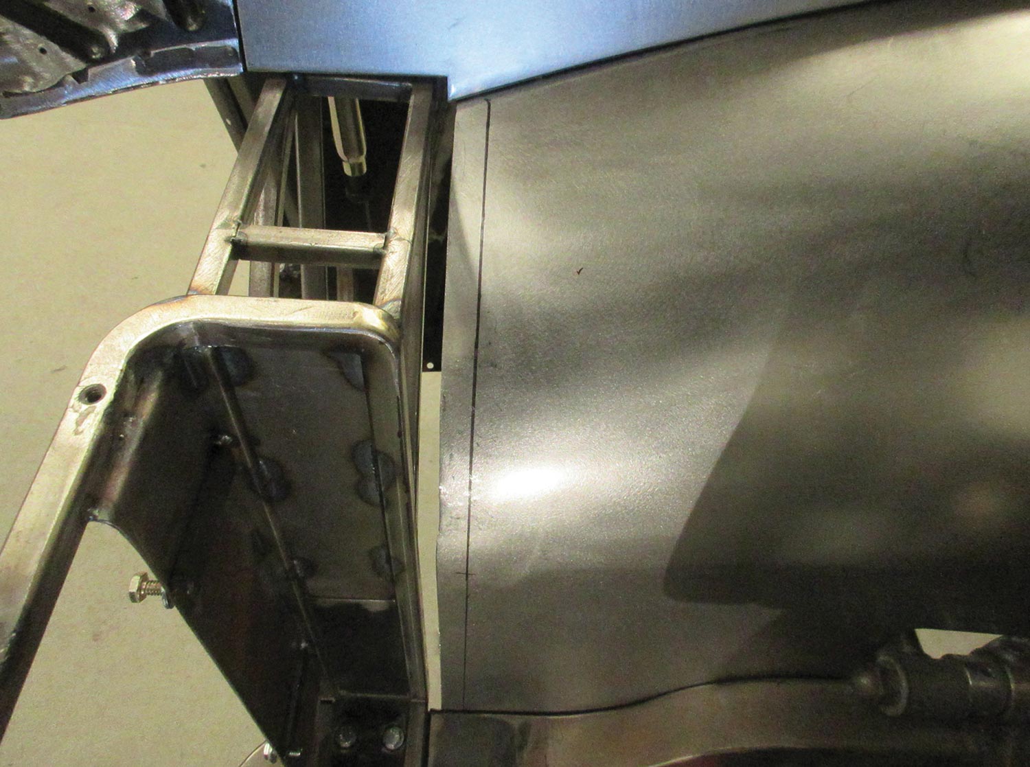
1. The first step in constructing the inner fender panels was to modify the inner fender edges, filling the original holes for the mounting bolts and adding a flange so the new fasteners would be hidden.

The Souza F-100 typography

Part 4: Inner Fender Panels

BY Ron CovellPhotography BY THE AUTHOR

W

ork is continuing on the Souza F-100 at Gary’s Rods & Restorations. The most recent areas to be completed are the inner fender panels. The goal was to dramatically clean up the look of the underhood area and to use hidden fasteners to hold all the panels together. It certainly takes a lot of extra planning and work to make panels that fit perfectly when you don’t want the screws to show, but this level of detail has come to be expected for high-end builds like this one, and everyone involved is delighted with the outcome.

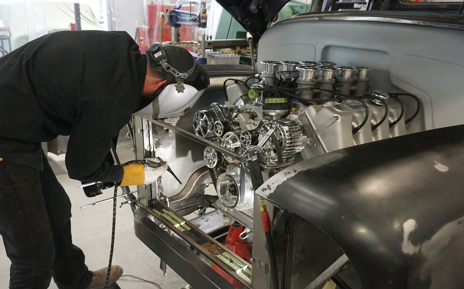
The original front fenders were joined to the inner fender panels with a long row of bolts, and the bolt heads make the joints look pretty “busy.” It took a lot of creativity to devise a system to hold all the panels snugly together while positioning the fasteners where they can be accessed from the back side but be hidden from view when looking underhood. The basic strategy is to put flanges on the edges of all the sheetmetal panels and locate the fasteners on these flanges. With a carefully configured design this allows all the joints to be pulled together snugly, but it does require a high degree of precision with the metalshaping. Gary’s relies on Emilio Belmonte to do the majority of this work; his craftsmanship is a delight to see.

As with most projects like this, making paper patterns is a good way to get started since it’s quite easy to cut, trim, and even discard a lot of paper as the design develops, but once the patterns are finalized, often one pattern can be used to cut the blanks for both sides of the vehicle. Also, it’s very likely that after building one side you will find lots of ways to streamline the construction of the other side.

Great care was taken to ensure that the new inner fender panels provided adequate clearance for the large wheels and tires for all possible movements of the steering and suspension components. The front wheels go through a wide range of movement, going from full right to full left steering lock, in the full bump and full droop condition. You don’t want to find out too late that there isn’t quite as much clearance as you would like!

When panels require flanges on the edges there are a variety of techniques that can be used. Long straight flanges are usually made on a sheetmetal brake, but if the flanges need to be curved other strategies may be employed. In some cases, flanges can be shaped over a hammerform, or with a tipping die on a beading machine, but for most of the long flanges on the inner fender panels, the flange was formed as a separate part and then welded to the main panels. When using this type of construction, it’s generally a good idea to avoid welding on the corners of a panel, so a good strategy is to bend an angle from sheetmetal, then contour it as needed by working the flanges with a shrinker and stretcher. When this angle is welded to the larger panel it positions the weld in a place where it’s much easier to work out the distortion, and the brake-formed corner will be very smooth and consistent. This is one of the hallmarks of high-quality metalwork.

There are many other tricks of the trade that the photos will display, so follow along as we show you how this complex assembly of panels was designed, fabricated, and finished. There’s a lot going on here that could be useful for your own projects!
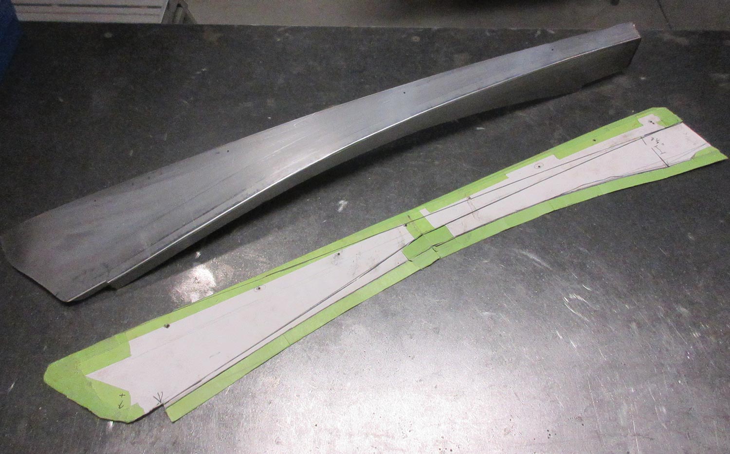
an inner fender panel and the paper pattern used to make it sit next to each other on a work surface
2. The inner fender panels were made in two pieces on each side. The paper pattern for the upper piece is shown here, along with the first piece of metal made from the pattern.
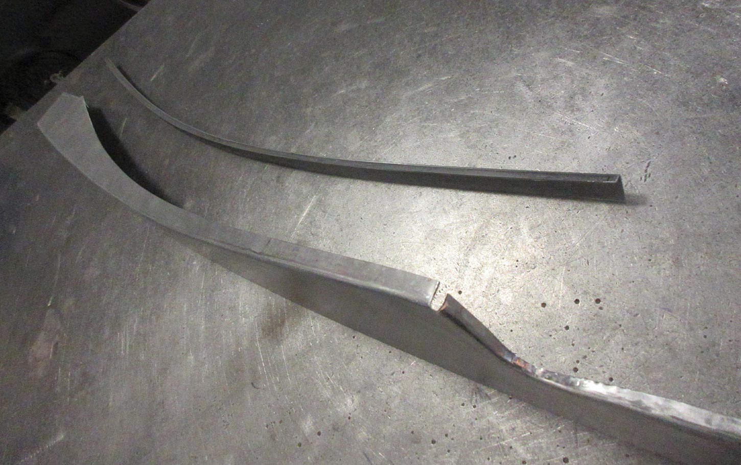
a bent strip of metal sits next to the first panel, both with matching contours
3. A strip of metal is bent in a brake to form a small flange, then contoured to match the first panel. This ensures the corner radius will be uniform.
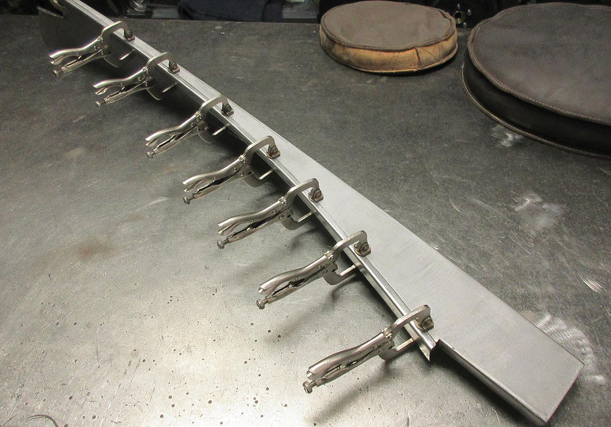
the flange is clamped in place on the panel
4. The flange is clamped in place here. The welds are positioned so the distortion from welding can be easily worked out.
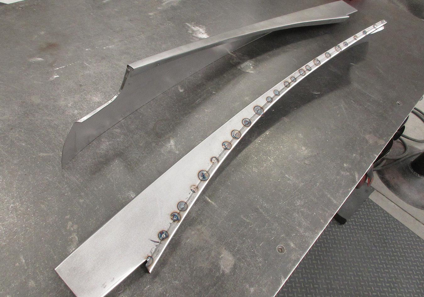
the panel with the clamps removed and the flange attached with closely spaced tacks
5. After a number of closely spaced tacks are made, the clamps can be removed to facilitate finish welding the joint, using the TIG process.
close view of the upper panel with the welds cleaned up
6. Here’s how the upper panel looks with the welds cleaned up.
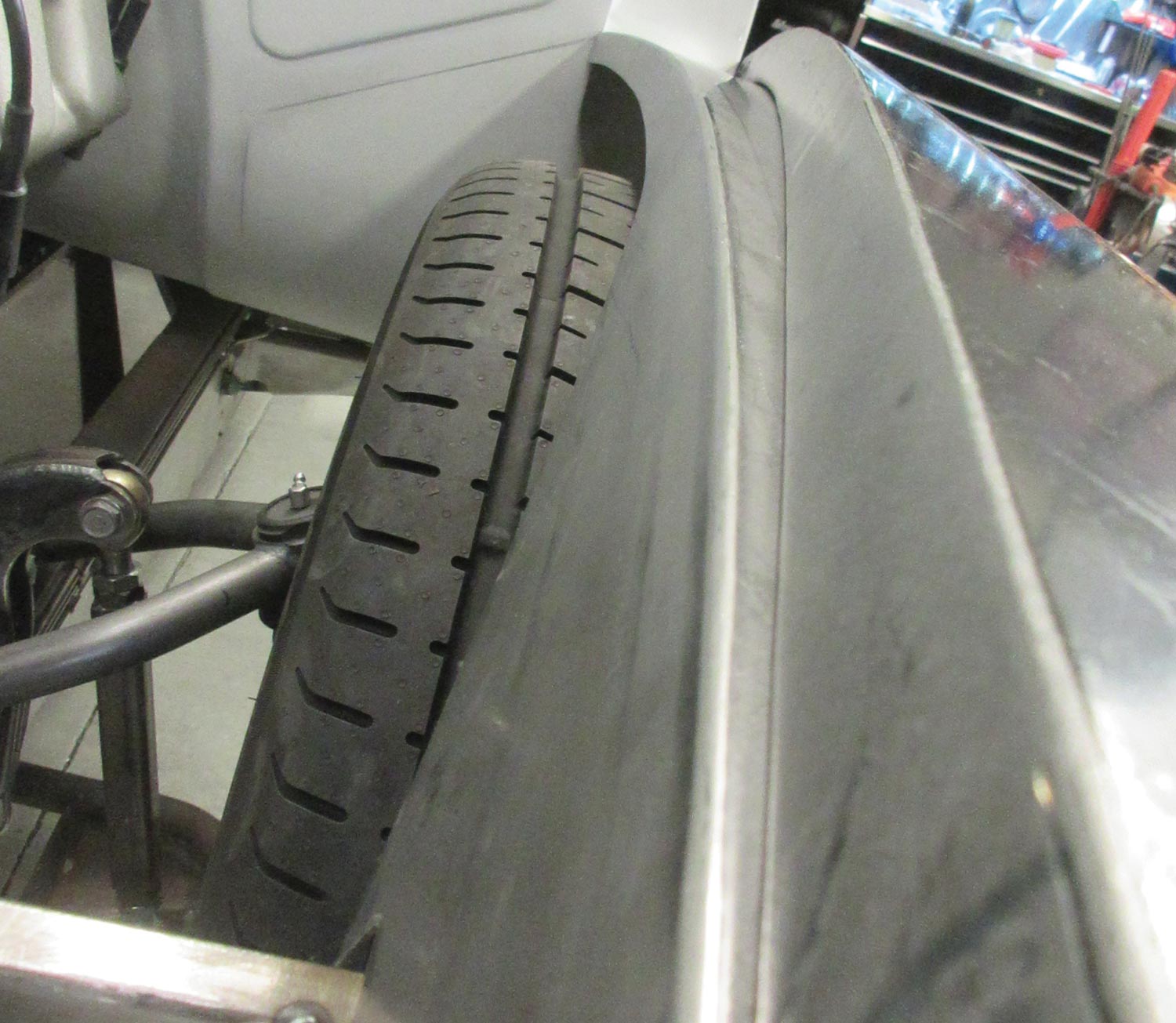
view along the fender area above the tire, the panel sits in place
7. With the panel in place, you can see how well it fits and appreciate the lack of any visible fasteners.
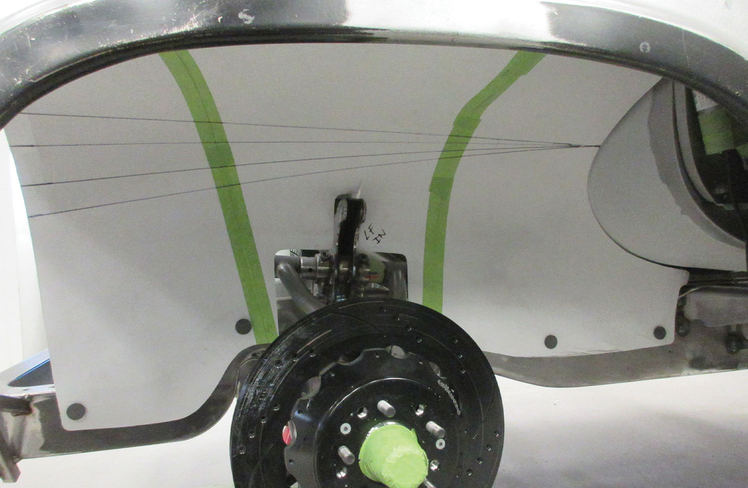
with the top panel positioned, a paper pattern is made for the lower panel
8. With the top panel positioned, a paper pattern is made for the lower panel. This complex part will be made in two pieces.
close view of the brake lines beneath the car
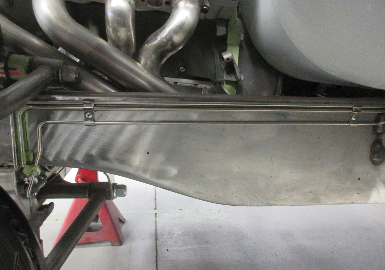
9. One obstacle the inner panel needs to clear are the brake lines.
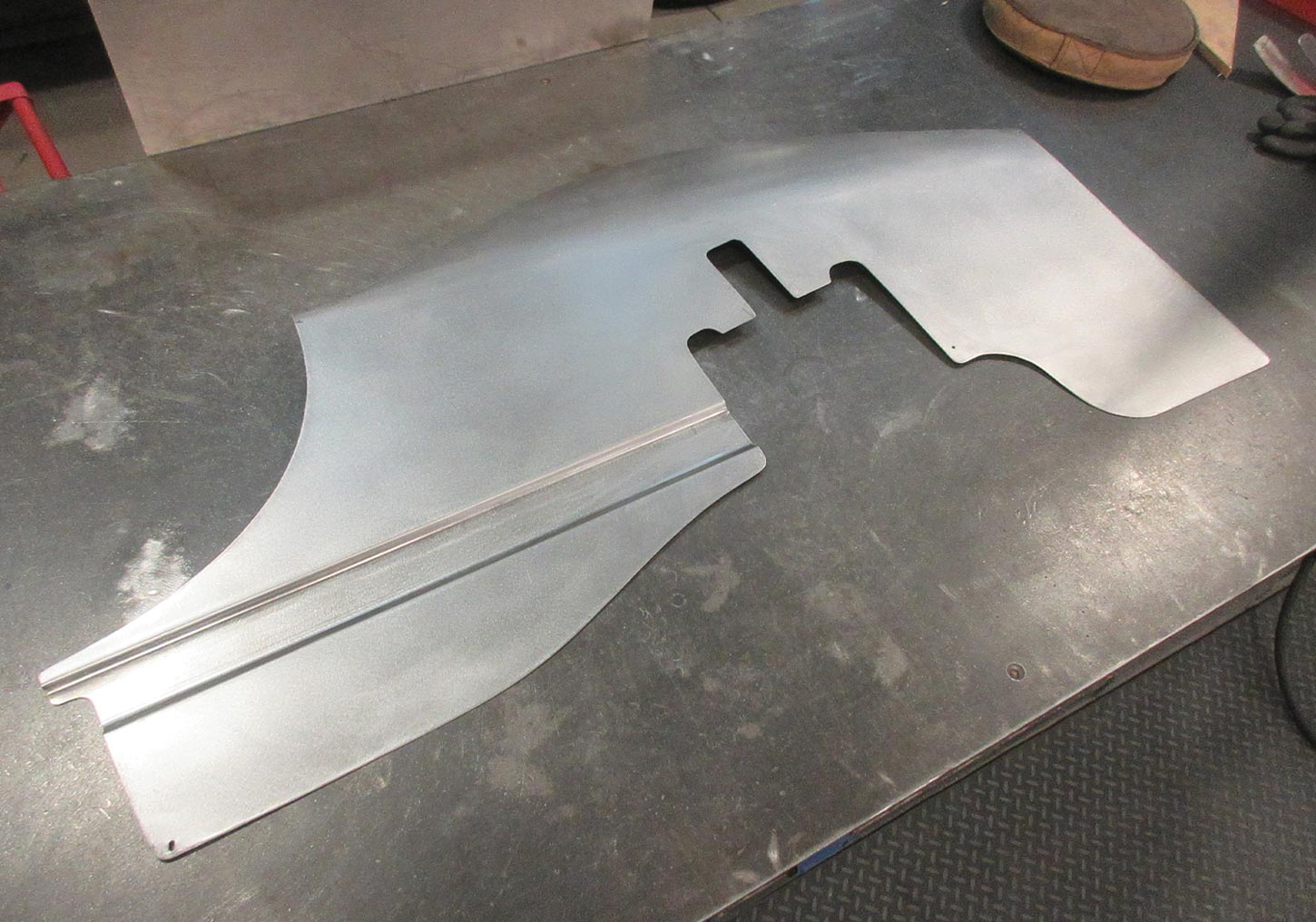
the lower brake panel with a channel formed to clear the brake lines
10. Here’s the lower panel formed in metal. Note how a channel was formed to clear the brake lines, ensuring a very clean look from inside the wheelwell.
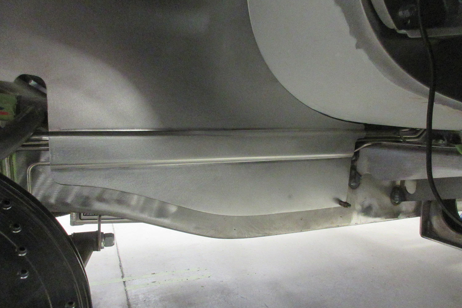
with the panel mounted, you can see how the channel neatly encloses the brake lines
11. With the panel mounted, you can see how the channel neatly encloses the brake lines, protecting them from damage and presenting a smooth look.
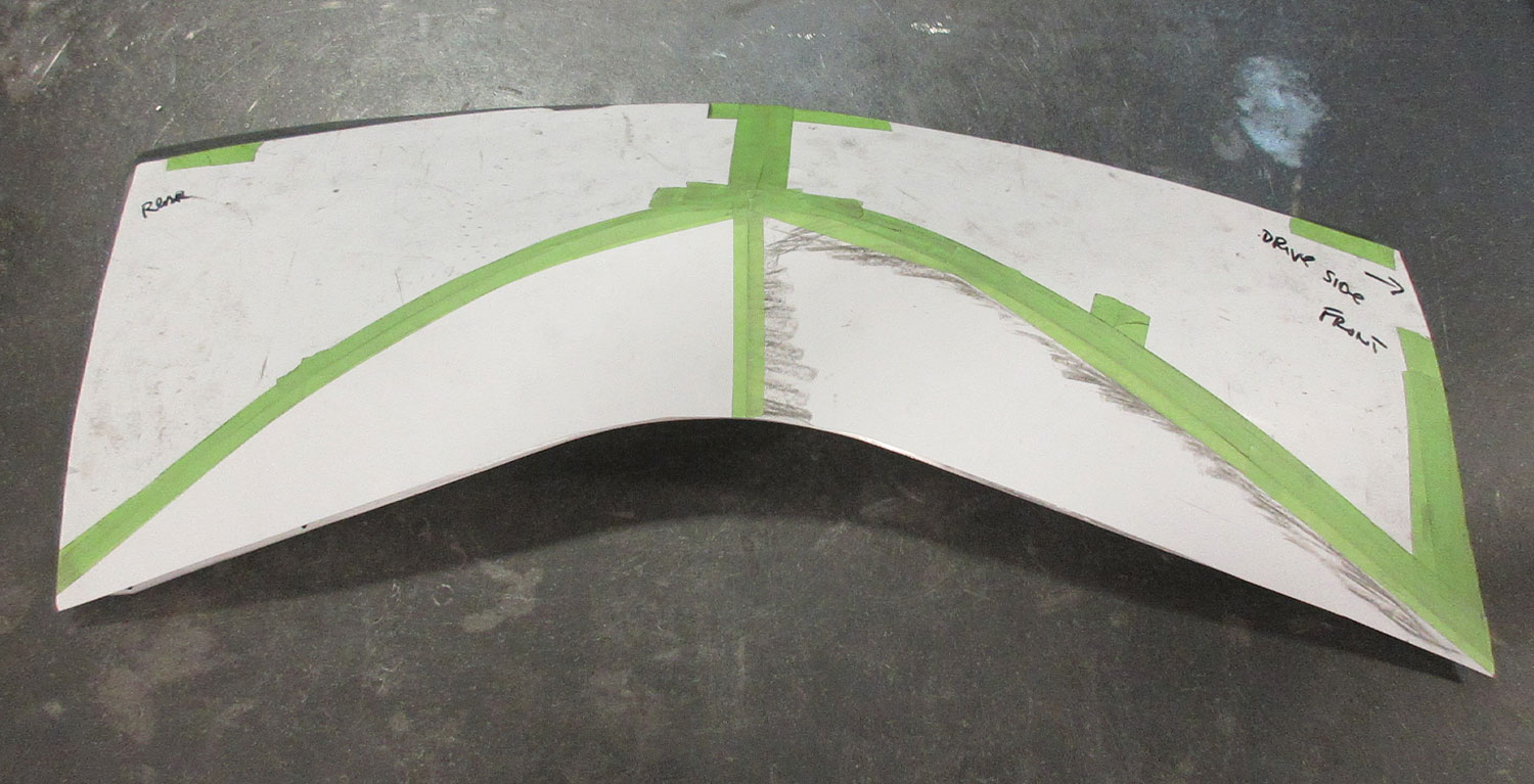
a paper pattern for the upper portion of the new panel sits on a work surface
12. This is the paper pattern for the upper portion of the new panel. This will be a tricky part to form.
the rough-shaped panel is test-fitted in place
13. The panel is rough-shaped, primarily by using a deep-throat shrinker and an English wheel, and here it’s being test-fitted into place.
the shaped and trimmed panels are tack welded together
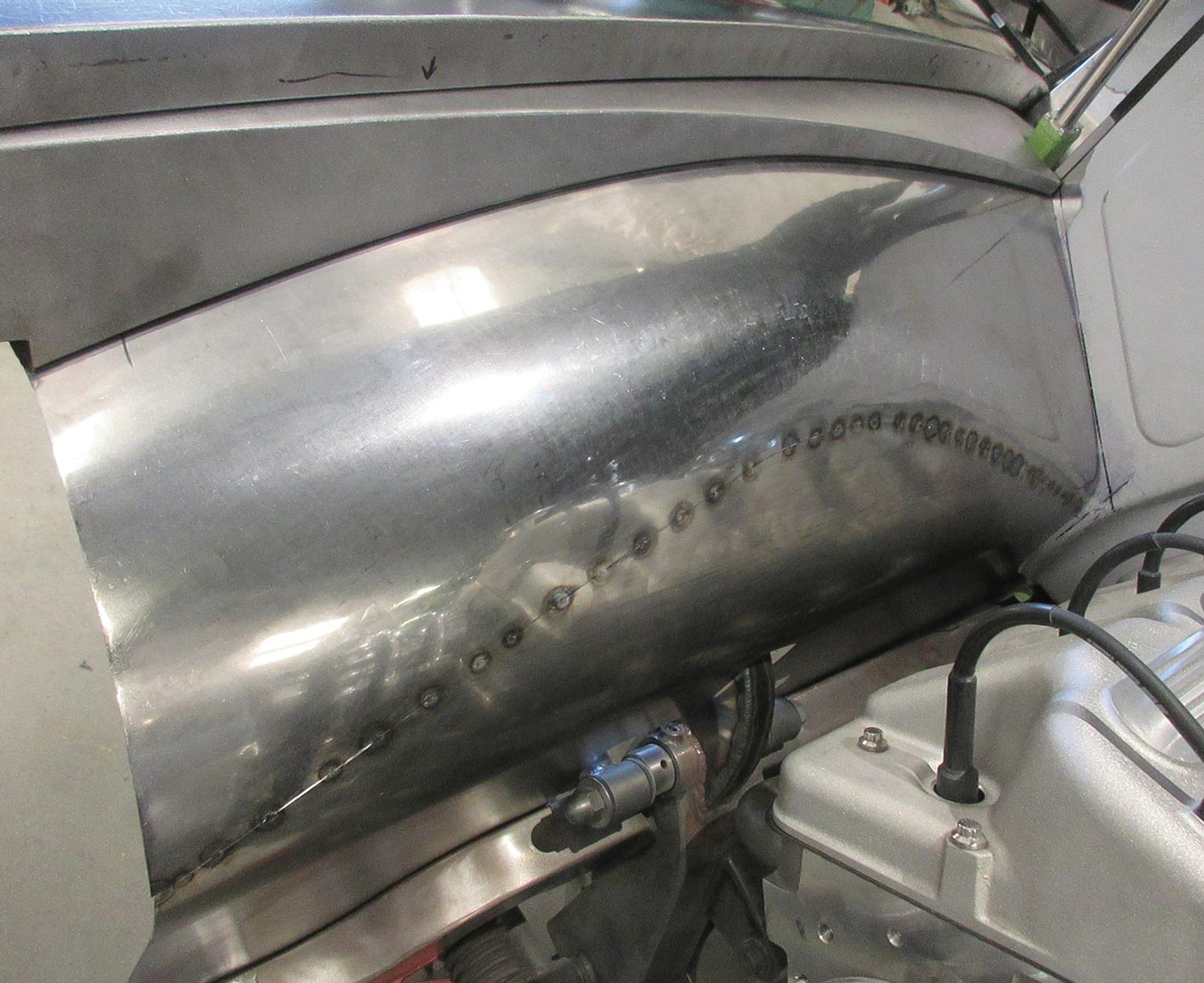
14. Once the panels are shaped and trimmed to fit neatly together they are tack welded together.
after finish welding, the mechanic smooths the welded area with a pneumatic planishing hammer
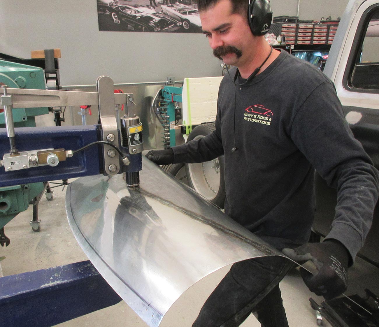
15. After finish welding, the welded area is smoothed with a pneumatic planishing hammer.
a flange is shaped to weld to the inner fender panel
16. This is a flange being shaped to weld to the inner fender panel, allowing it to be bolted to the firewall.
a small angle will be added to the front portion of the panel, ensuring a snug fit against the core support and allowing the fasteners to be hidden from sight
17. A small angle will be added to the front portion of the panel, ensuring a snug fit against the core support and allowing the fasteners to be hidden from sight.
the angle is fitted and is tack welded into place
18. The angle is fitted here and is being tack welded into place.
car fender with both panels installed
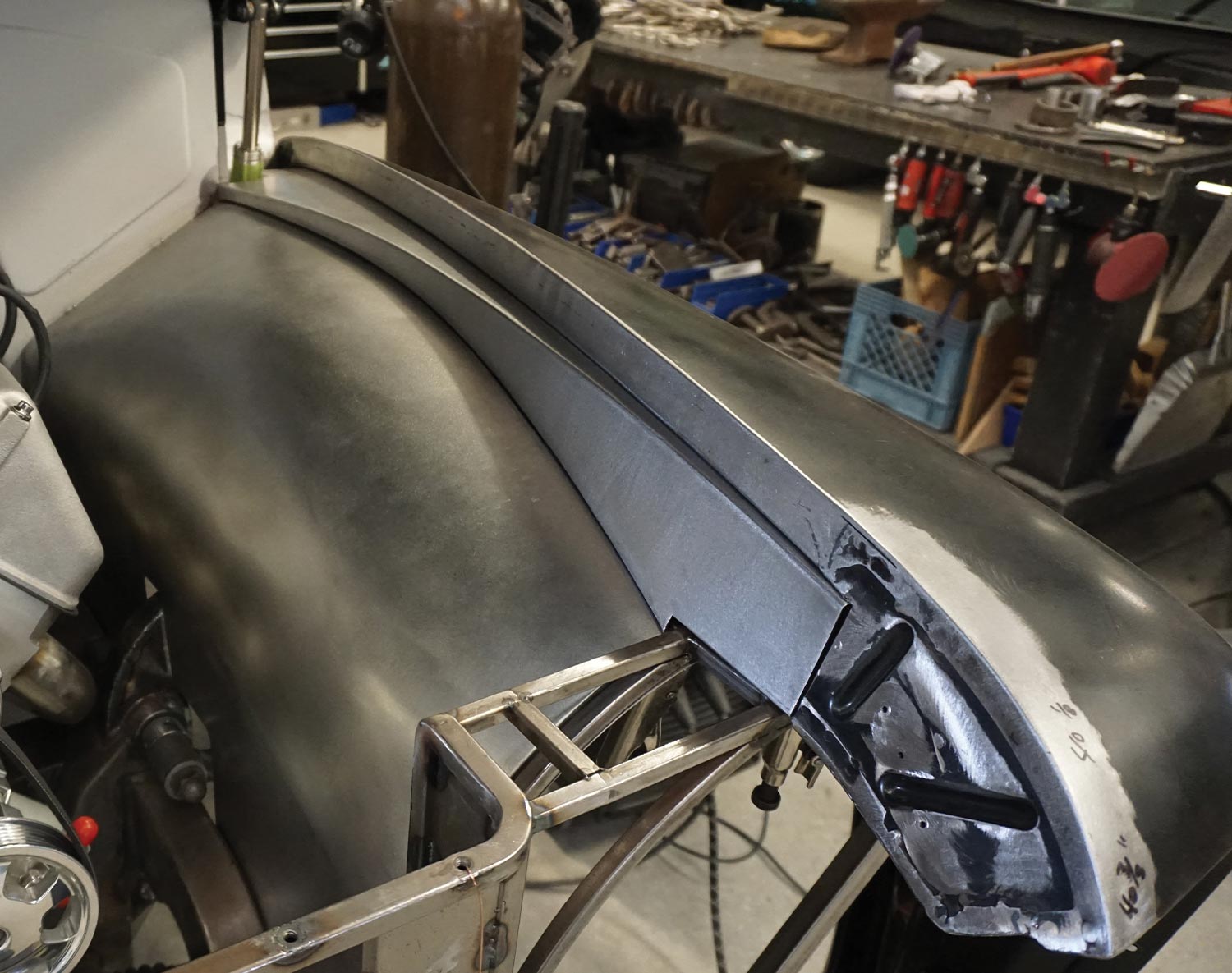
19. With both panels installed, you can see how beautifully they fill in the side of the engine bay.
close up of the surface quality of the fenders metal panels
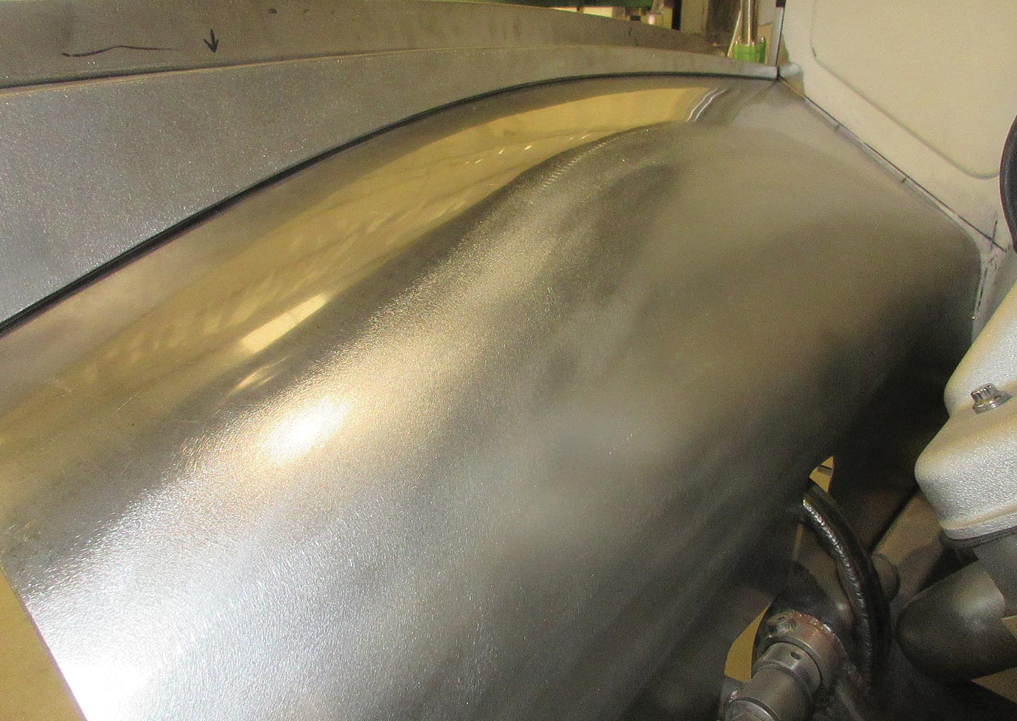
20. Take a close look at the quality of the surface finish. It takes special care to get metal panels to be fitted and smoothed to this level, but that’s the sign of a top-level job.
Gary’s Rods & Restorations
(831) 728-7025
garysrods.com