
 Tech
Tech
BY Ron Ceridono  Photography by The Author

BY Ron Ceridono Photography by The Author
Flat Out’s Vette-Based IRS for Early F-100s
Flat Out’s Vette-Based IRS for Early F-100s
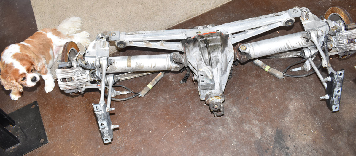
hen it comes to suspension design there’s a reason many high-end luxury and performance cars have independent rear suspension: it’s the simple fact that an IRS rides and handles far better than a solid axle. Like many classic truck enthusiasts, Paul Willis wanted to improve the ride and handling of his ’55 Ford F-100 with an IRS update, but the heart-stopping cost of the aftermarket designs put such a swap out of reach. That was before he learned of Don McNeil’s Flat Out Engineering installation kits that use C4 Corvette suspension components.
McNeil has a long and storied career as a hot rodder and entrepreneur. He’s been involved in drag racing, Bonneville competition, built a long list of modified cars and trucks, as well as developed a variety of successful businesses. Today McNeil’s focus is Flat Out Engineering that specializes in affordable, easy-to-install kits to adapt ’84-96 Corvette C4 suspension components to a variety of cars and trucks—that includes a kit for the rear of our ’55 F-100.
As McNeil explains it: “The C4 Corvette suspension was a design milestone in sports car suspensions. GM engineers worked for years on this to have a ‘World Class Sports Car’ that would outperform the finest high-priced European sports cars on the market. The forged aluminum spindle uprights, A-arms, half shafts, and control arms are not only light weight but incredibly strong. The lightweight aluminum components give the suspension system a sprung to unsprung weight ratio that is unsurpassed. This provides excellent ride quality with cornering and handling that outperforms any other production vehicle.” McNeil points out another big advantage to the C4 suspension is the availability of parts. “Ball joints, brake parts, tie-rod ends, and any other parts that might wear with frequent use are standard GM parts and easily available at parts stores anywhere.”
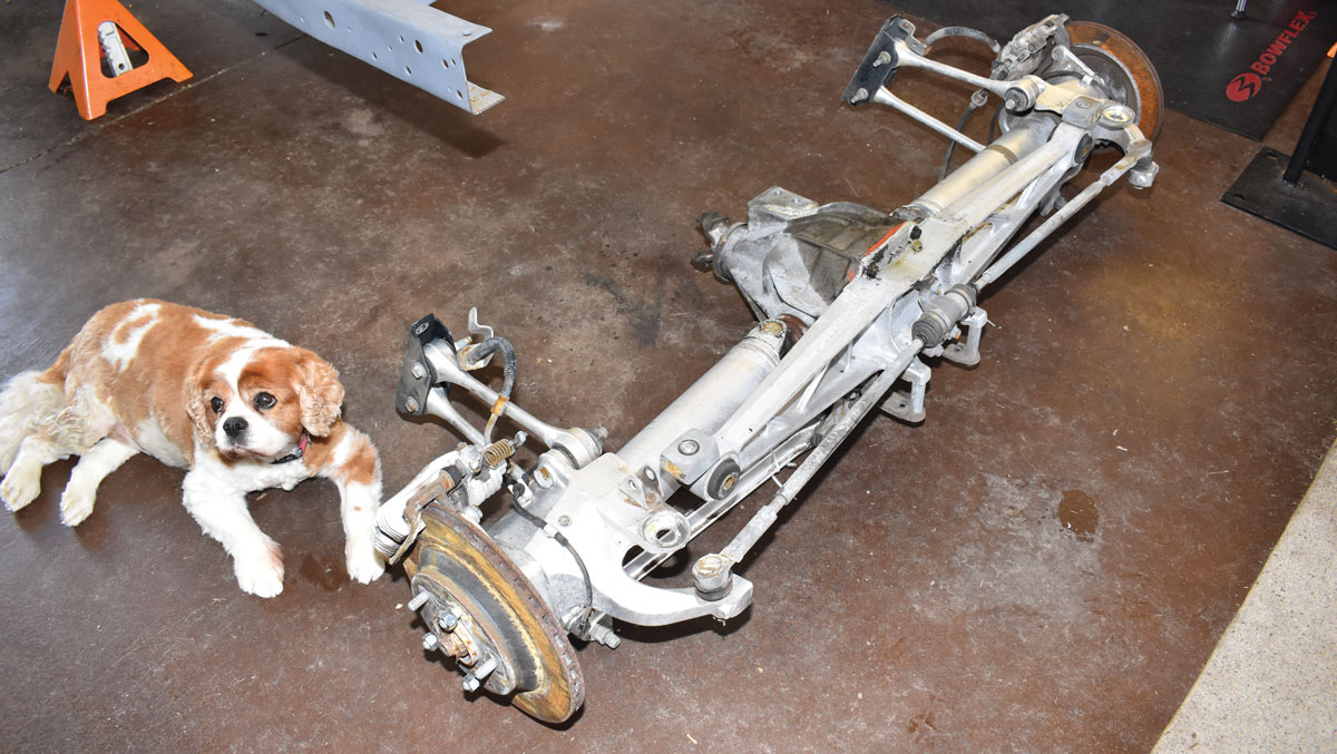
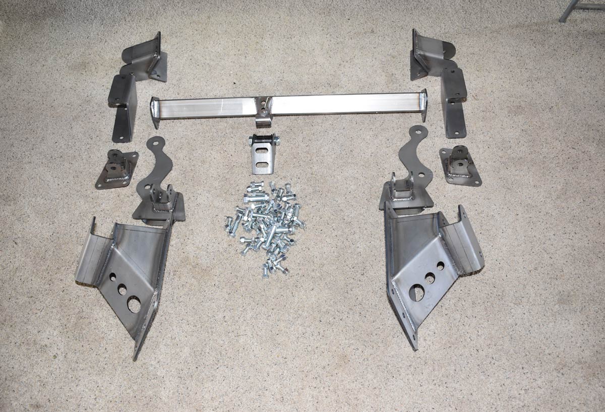
To install a C4 IRS under a ’53-64 Ford pickup there are two kits available. One is for use with ’84-87 Corvette rearends, the other is for ’88-96 style. Both kits maintain the correct geometry and handling characteristics C4 Corvettes are known for. Each kit includes bolt-on style rearend mounting brackets, pinion mounting crossmember and pinion snubber bracket with urethane bushing, upper and lower coilover shock mounts, rear boxing plates, forward control arm mounting brackets, all necessary hardware, and detailed installation instructions.
During the production run there were two versions of the C4 IRS. The ’84-87 version is 61 1/2 inches wide wheel flange to wheel flange and uses parking brakes inside the rotor hats. The ’88-96 is 1 inch wider; 62 1/2 inches and the parking brakes are built into the caliper. Both series of rearends use the 5-on-4.75 wheel bolt pattern, the same as Chevrolet passenger cars, so there are many styles of wheel to choose from. From the factory, ’84-87 C4s used 16-inch wheels; in 1988 16-inch wheels were standard with 17-inch on special models; ’89-96s all used 17-inch wheels.
Another difference in C4 rearends is the centersection. Both generations came with either a Dana 36 or Dana 44. Factory gear ratios for the Dana 36 include 2.59:1, 2.73:1, 3.07:1, and the rare, hard-to-find 3.31:1. Dana 44s can be found with 3.07:1, 3.33:1, or 3.45:1. Of course there is a wide range of gear ratios available for both the Dana 36 and 44 from the aftermarket.
Installing Flat Out Engineering’s C4 IRS kit is surprisingly simple. The instructions are easy to understand and follow, with all the necessary measurements included. All the brackets bolt into place with no welding. While the kit is easy to install it’s wise to clamp all the brackets in place and double check all the measurements before drilling any holes.
Along with the basic installation kit we opted for two Flat Out Engineering options. We added the “Free Spirit” Adjustable Rear Control Arm Kit. It replaces the four stock Corvette strut rods and eliminates the “bind” produced by the rubber or urethane bushings in those rods by incorporating premium spherical rod ends. They provide increased suspension travel for a smoother ride and complete adjustability—plus they look great.
Another option we chose was the Tubular Rear Toe Bar Kit that replaces the stock Corvette assembly (it provides toe adjustment for the rear wheels and maintains it during suspension travel). The replacement kit lowers the bars by mounting to the bottom of the steering arms, thereby providing additional frame clearance in lowered ride height applications. This kit provides increased adjustability and with the billet mounting bracket and the tapered aluminum adjusters it enhances the rearend’s appearance as well—wait until it’s all polished and painted.
With an easy-to-install Flat Out Engine-ering kit and a readily available C4 IRS (ours came from Dino’s Corvette Salvage, corvettesalvage.com) you can give your classic truck the ride and handling qualities of a contemporary sports car for a price that won’t break the bank.
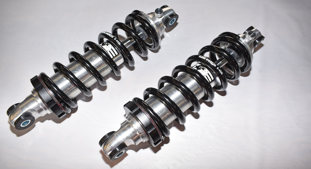
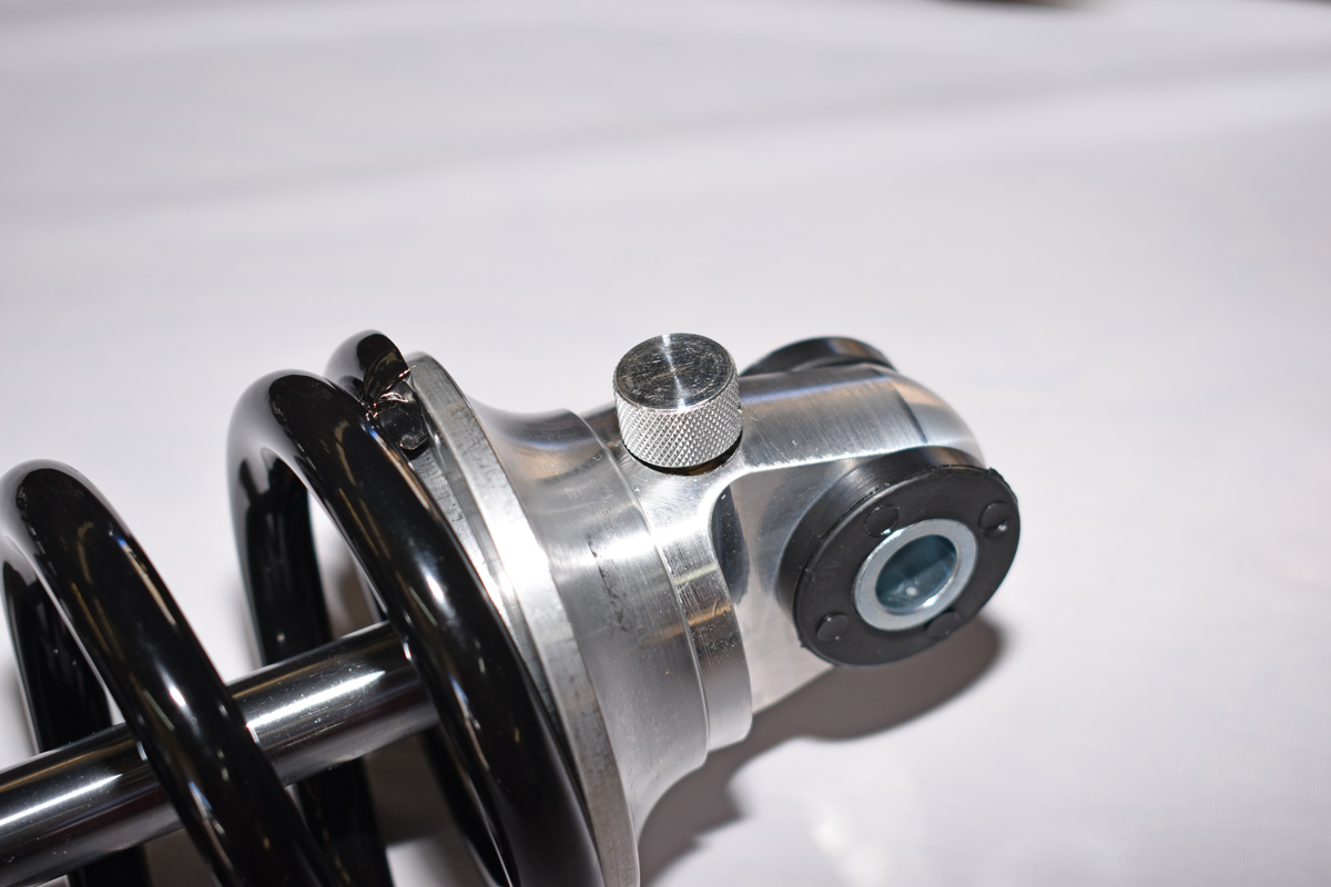
10. The knob at the top of the shock body adjusts rebound. Full counter-clockwise is the lowest setting. Turning the dial clockwise increases rebound stiffness.
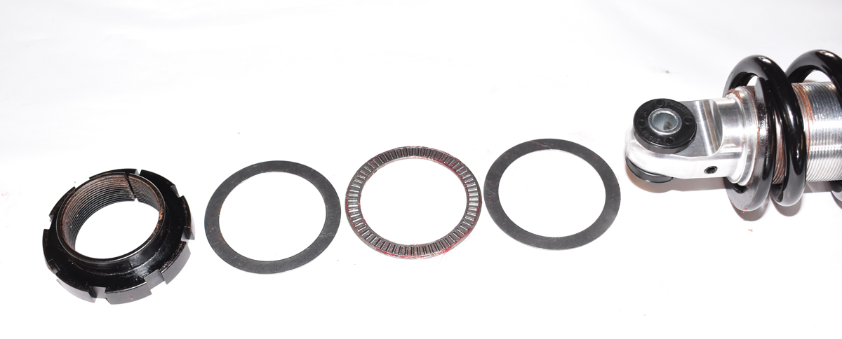
11. To make suspension tuning easier, Aldan offers a thrust bearing kit that fits between the adjuster and coil spring. The bearing reduces friction when adjusting the preload on the spring.
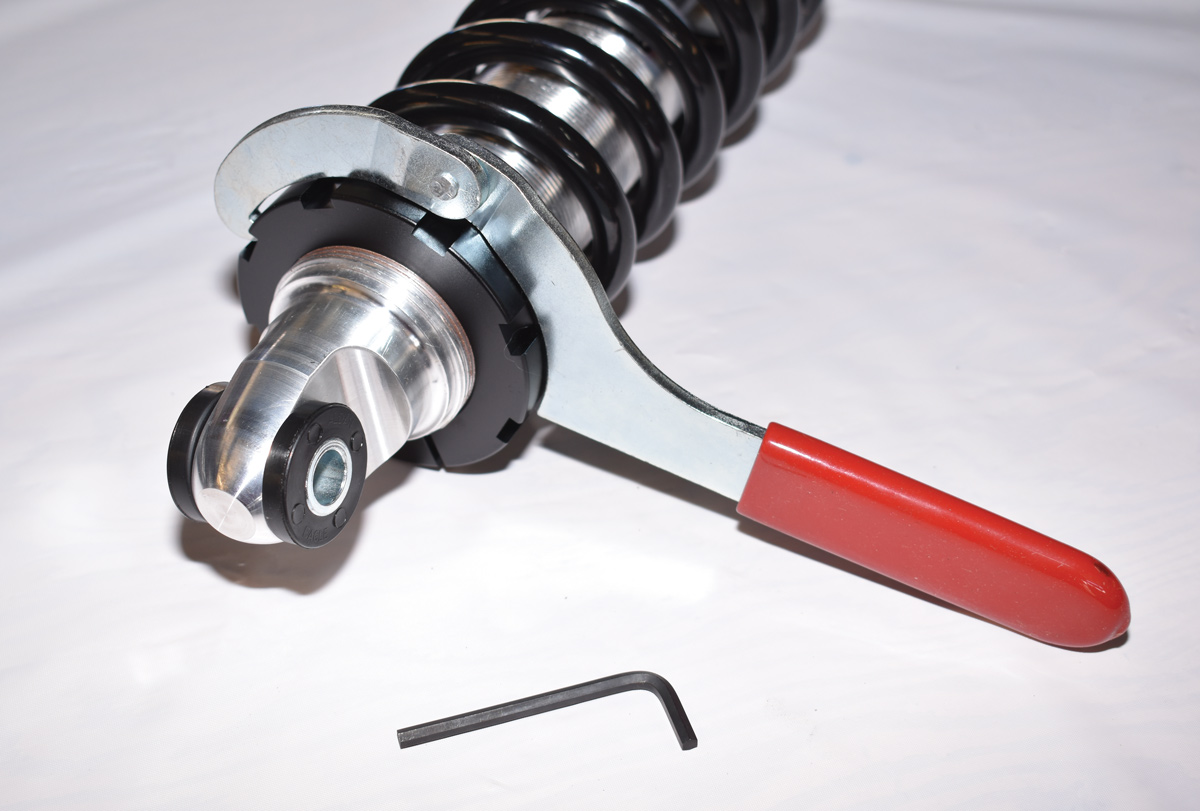
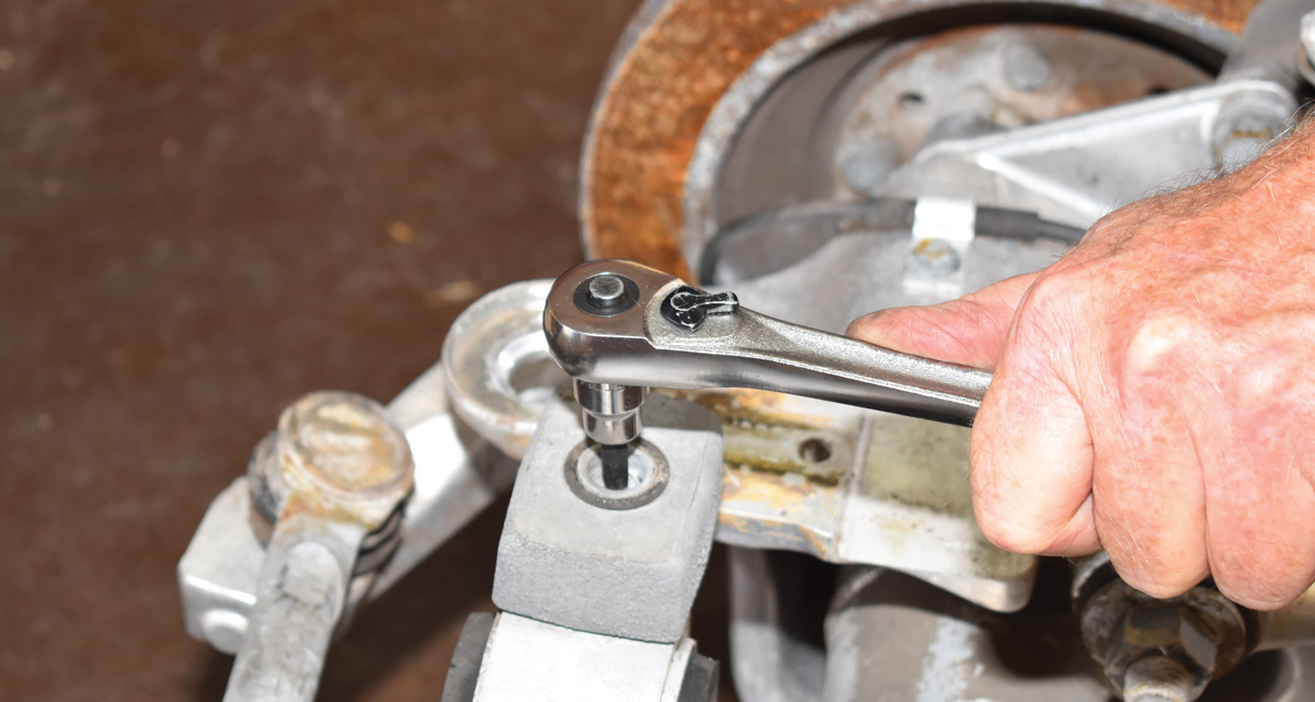
12. A spanner wrench is used to adjust the spring’s preload. A good starting point is to compress the spring 1 inch before installation.
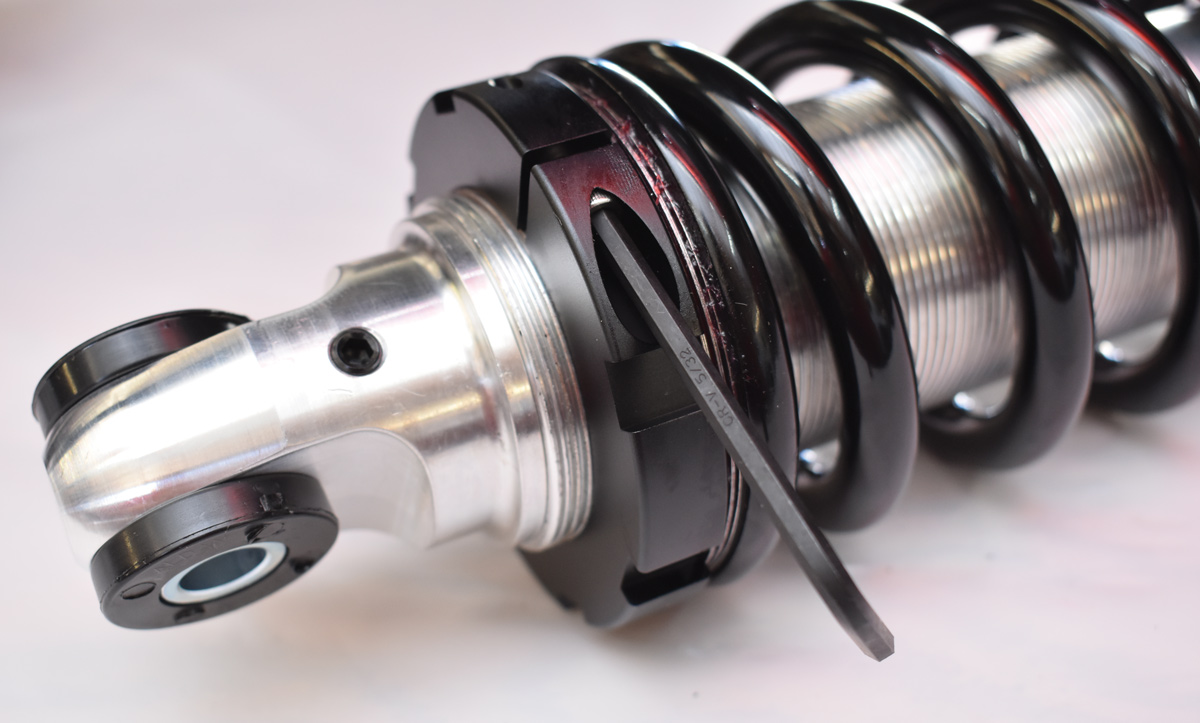
13. Once the final preload adjustment is made the threaded adjustment collar is secured with a setscrew.
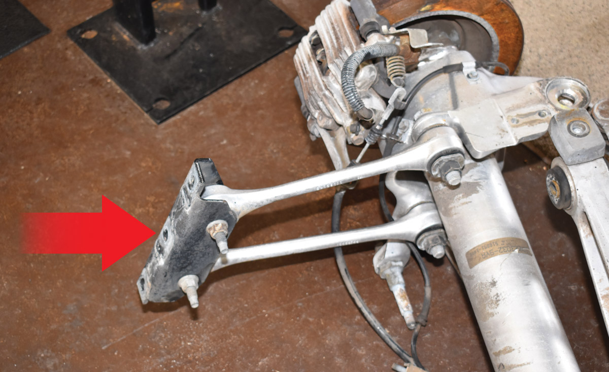
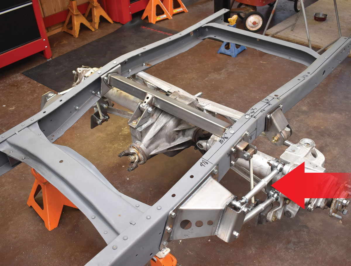
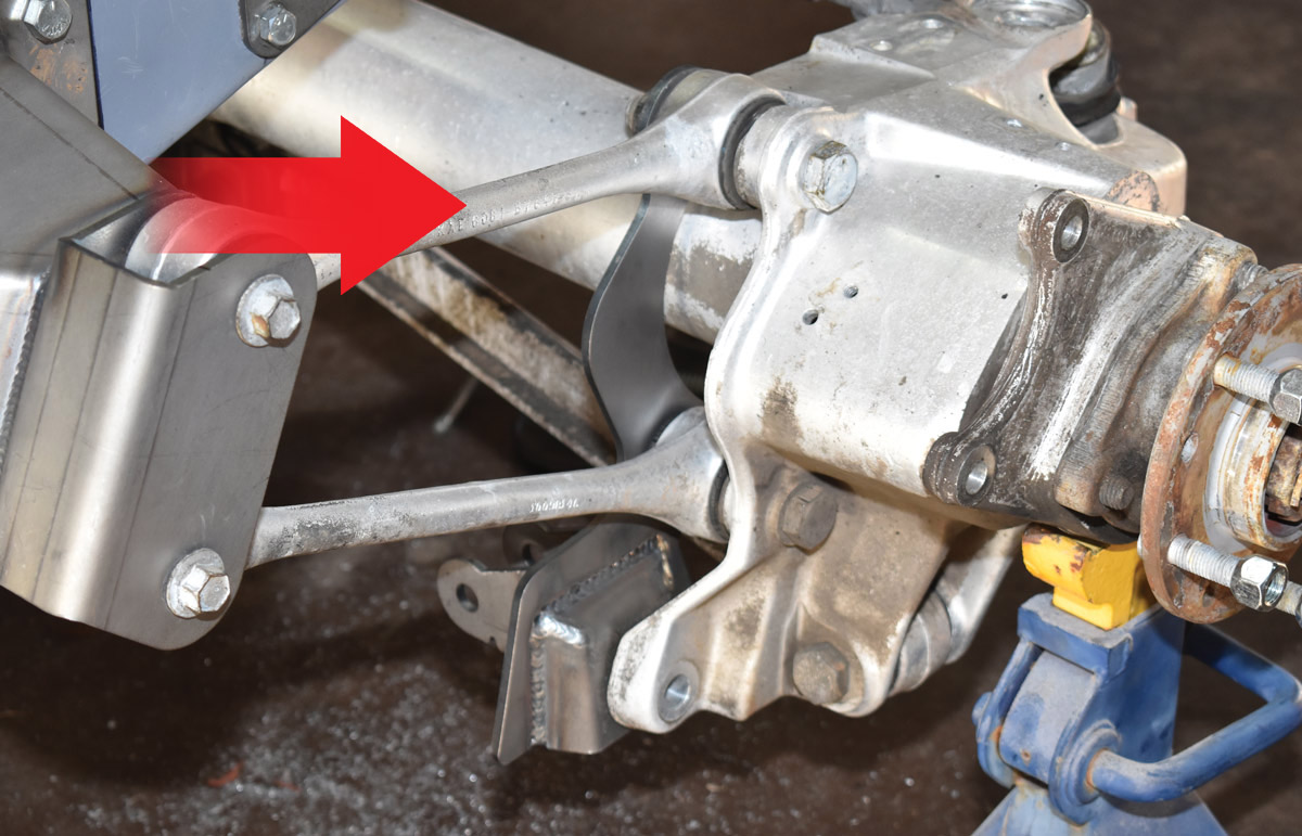
14. The stock Corvette control arm bracket (arrow) is removed—the arms will attach to the new frame brackets that are part of the installation kit.
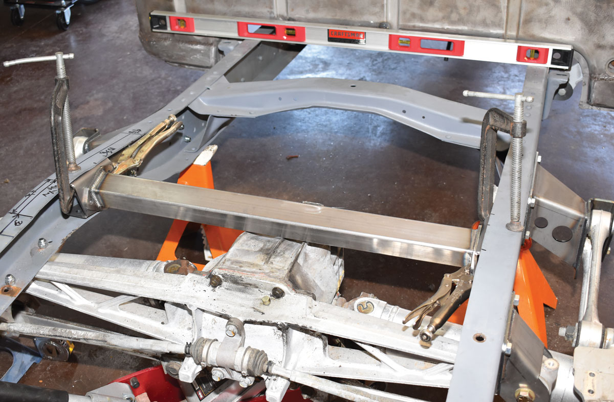
15. Before the IRS assembly can be slid into place under the framerails the square damper brackets on the Vette crossmember, or batwing, that mounts the differential case must be removed.
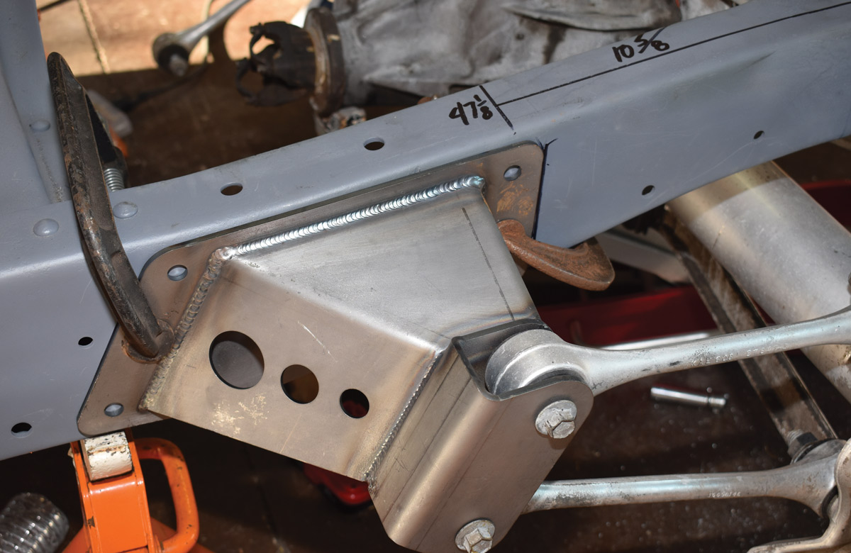
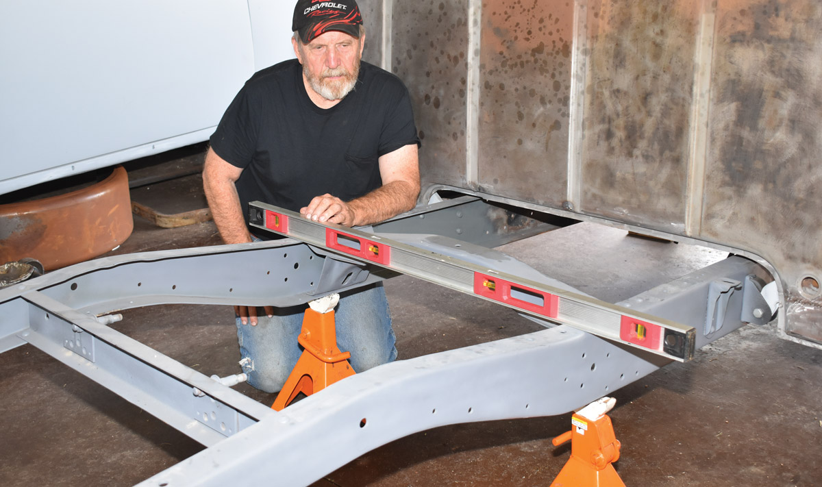
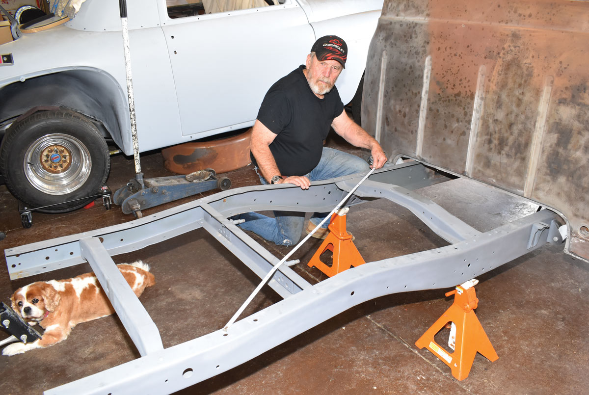
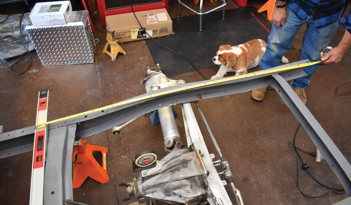
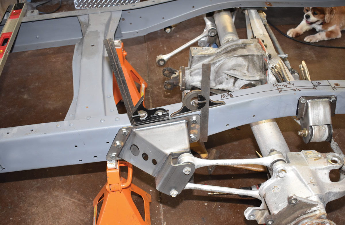
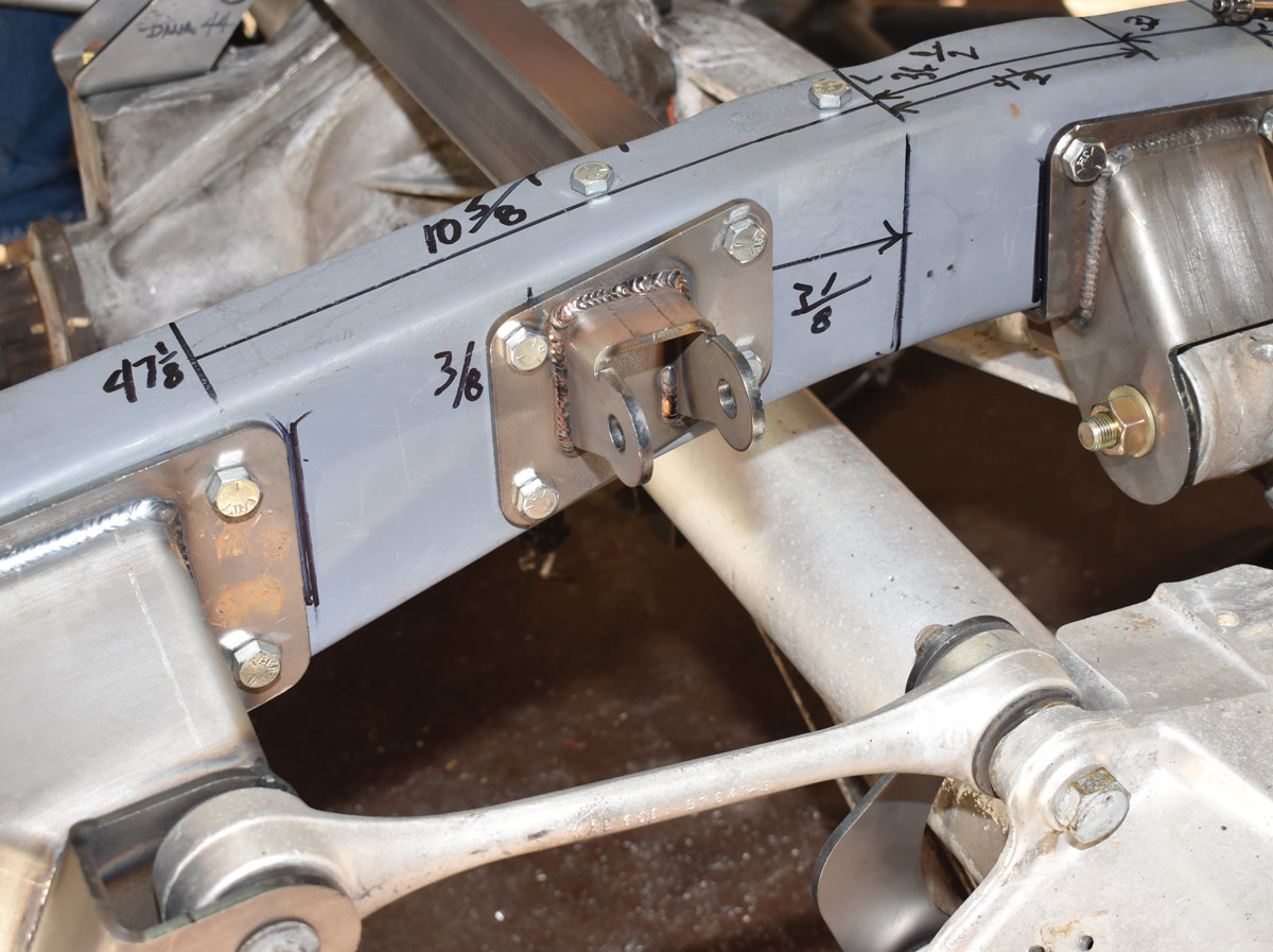
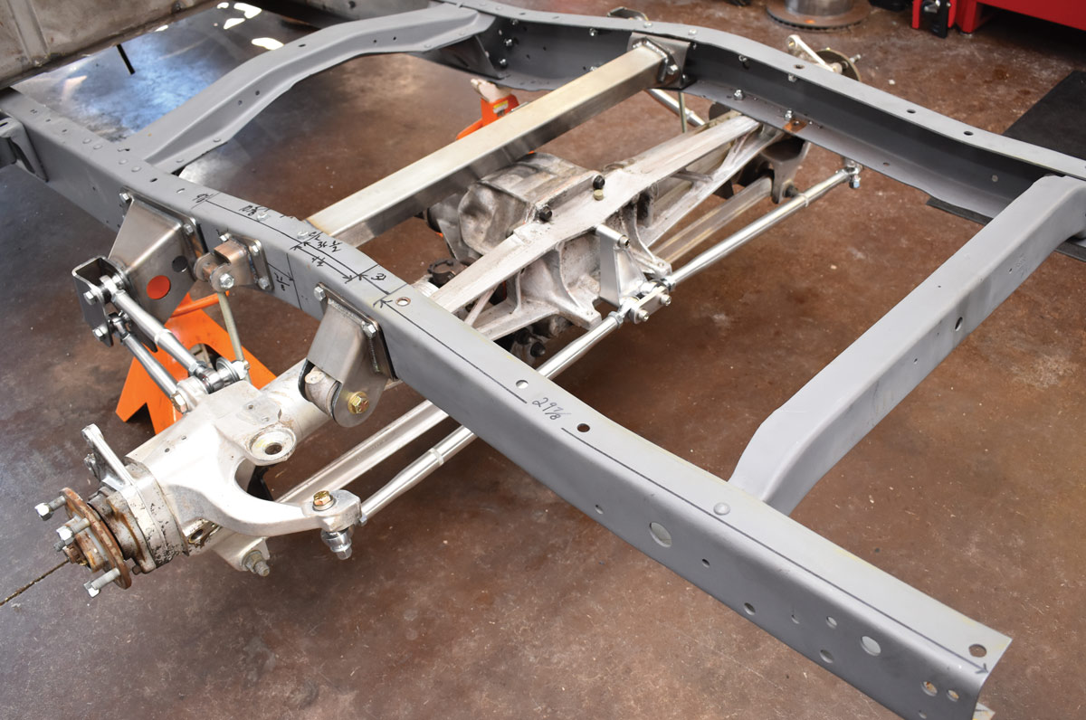
16. The front frame brackets are positioned 47 1/8 inches from the end of the framerails to the center of the rear upper mounting hole (10 5/8 inches from the axle centerline). We clamped everything in place and triple checked all the measurements before drilling any holes.
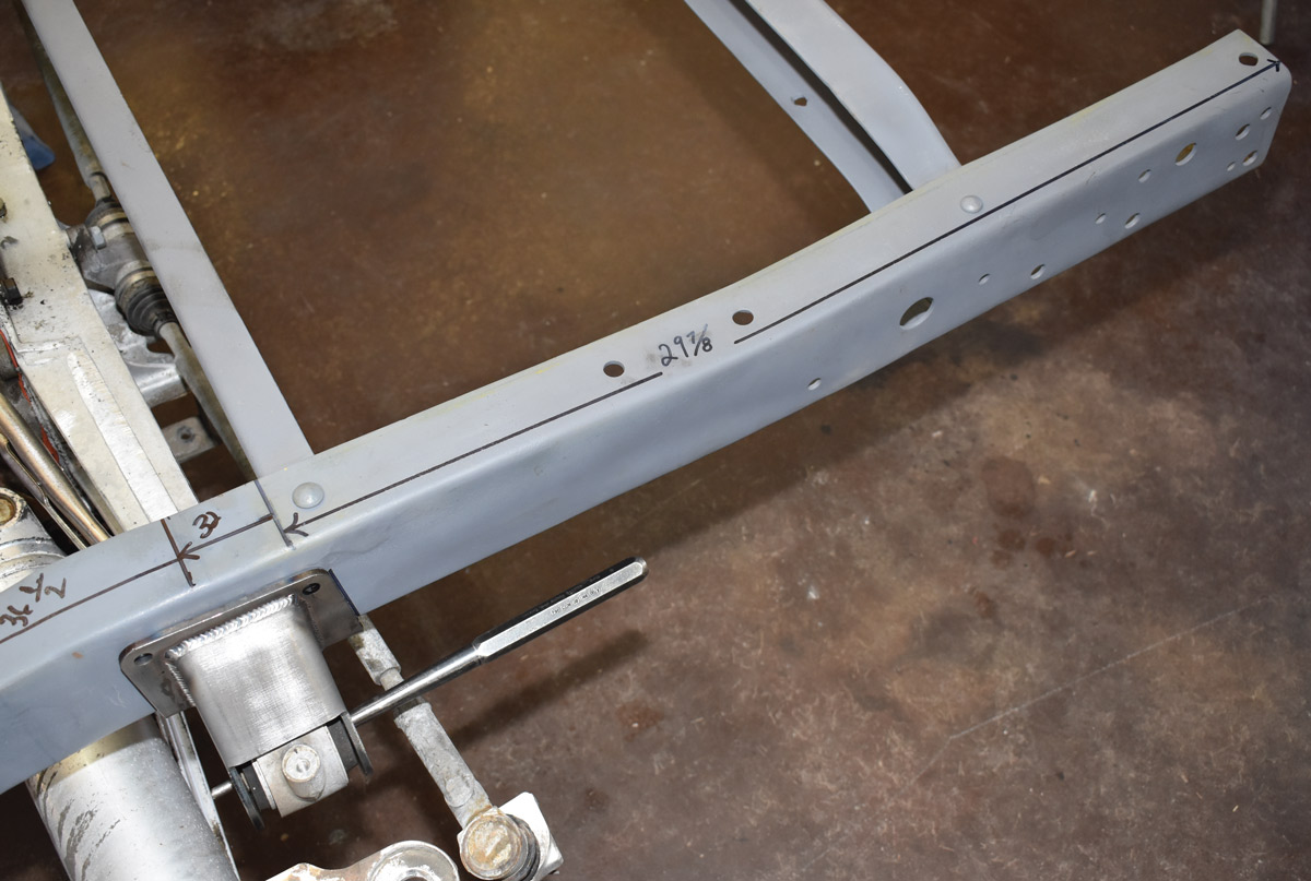
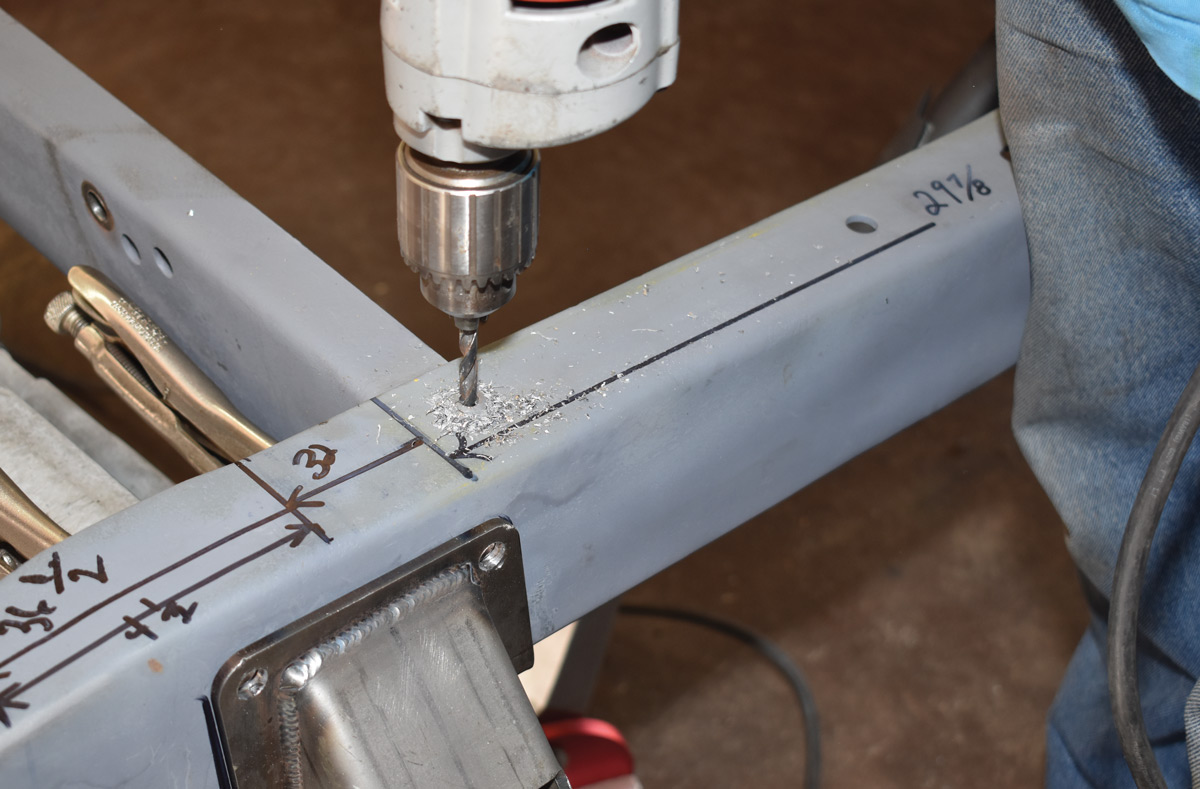
17. With the centersection supported on jackstands, the batwing brackets were positioned 29 7/8 inches to the center from the end of the framerails and clamped in place.
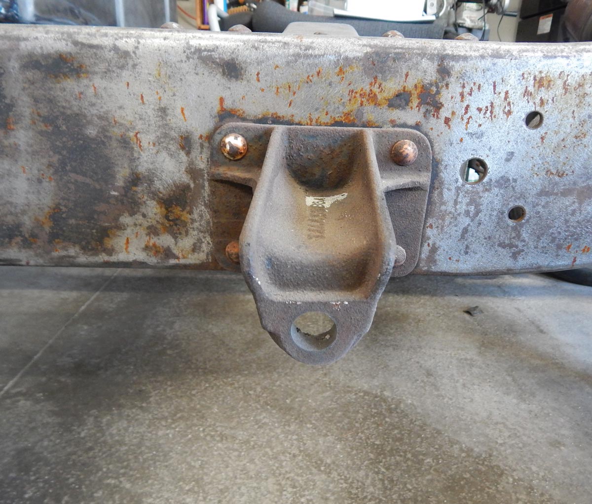
18. In our case rivets securing the stock F-100 shock absorber crossmember interfered just enough to keep the batwing brackets from fitting properly against the bottom of the framerail.
19. In addition with the stock Ford shock crossmember in place there wouldn’t have been room for a nut on the top right bolt for the batwing bracket. We could have ground off the rivet and notched the crossmember to provide clearance for the nut. We elected to remove the four rivets and eliminate the crossmember.
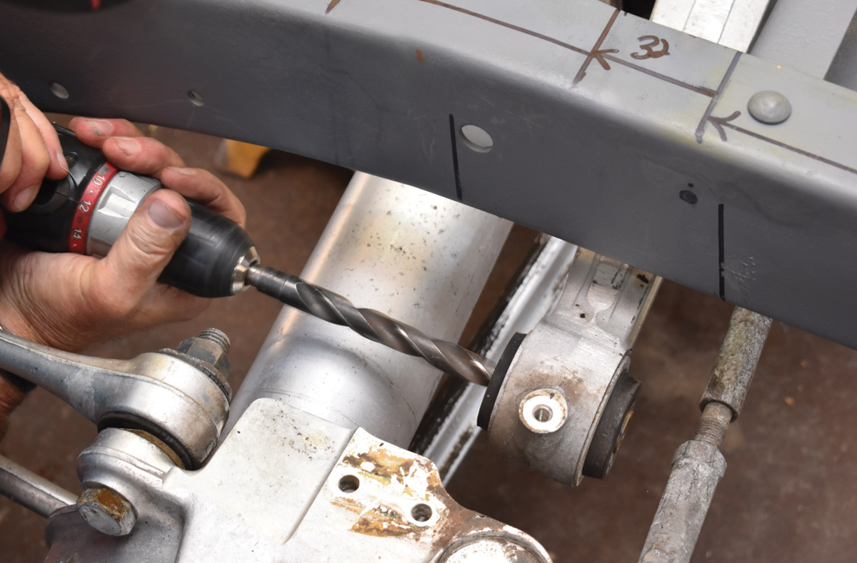
20. The Corvette batwing uses metric fasteners. To use the hardware supplied in the kit the inserts in the bushings must be drilled to remove projections in the sleeves that accommodate the metric bolts.
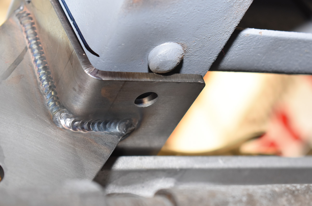
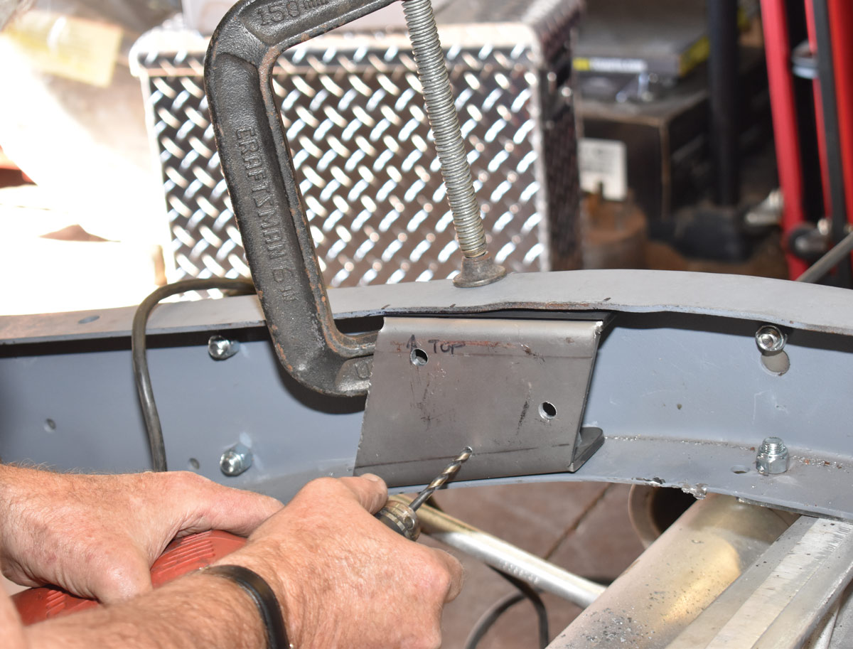
21. Satisfied that the radius rod and batwing brackets were properly located all the necessary holes were drilled. We used a tri-square, an angle finder, and the measurements in the instructions to duplicate the mounting position of the radius bracket on the other side of the frame.
22. Next to be installed was the crossmember that secures the centersection. With the pinion angle set at 2 degrees up, the crossmember was clamped in place.
23. The pinion crossmember has three parts, two frame brackets that bolt to the framerails and the crossmember that bolts to the brackets. With the pinion at the desire angle the holes in the frame bracket are marked and drilled.
24. With the crossmember bolted in place the supplied bracket is attached to the differential housing and bolted to the bushed bracket on the crossmember. A pair of temporary struts (one can be seen, arrow) were used to hold the suspension at ride height.
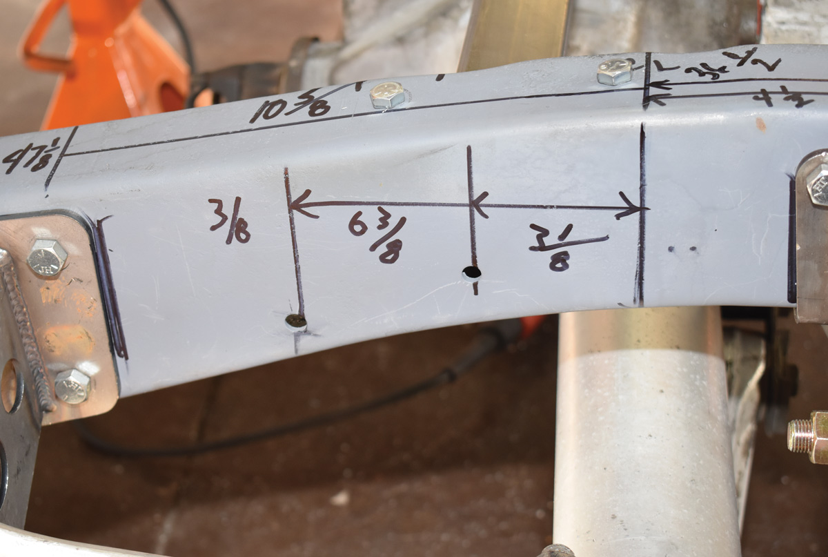
25. There are two factory holes in the frame at 3 1/8 and 6 3/8 inches forward of the rear axle center line. They are drilled to 3/8 inch and are used to attach the coilover brackets. Two additional holes must also be drilled.
26. Here all the frame brackets have been bolted in place. One last round of measurements verified all the brackets were precisely where they were supposed to be.
27. To attach the coilovers to the hub bracket (arrow) bolt to each hub. The brackets are attached by the radius rod bolts and the factory lower shock absorber mounting hole (shock stud has to be removed).
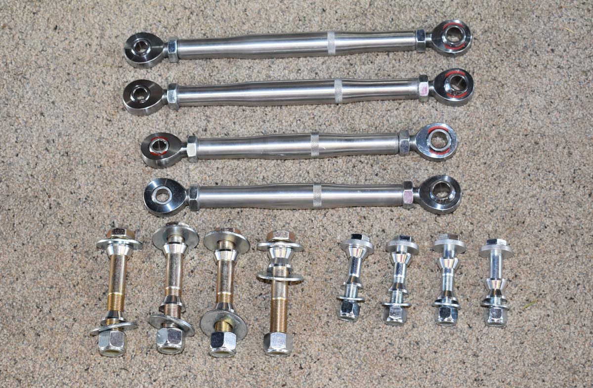
28. To dress up our installation, and to provide some adjustability, we opted to replace the stock control arms with Flat Out Engineering’s new aluminum adjustable links.
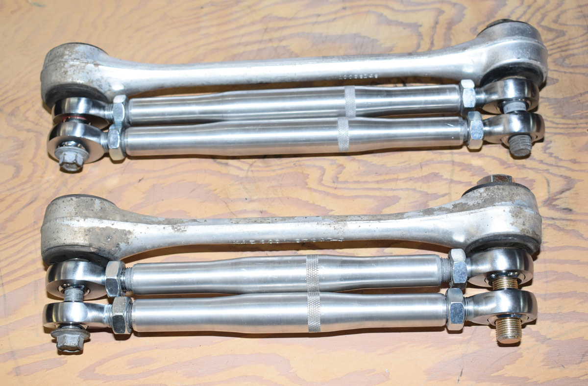
29. Before installation the length of the control arms was matched to the originals by aligning them with long bolts.
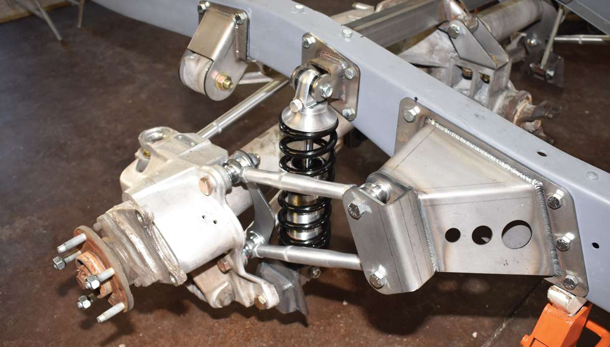
30. Here the Aldan coilovers and adjustable control arms are in place. The links’ rod ends are less restrictive to movement than the GM factory bushings.
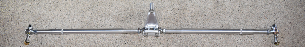
31. The final piece to be installed was the Flat Out Engineering tubular rear toe bar kit to replace the stock Corvette assembly.
32. All finished. It’s a credit to Flat Out Engineering that something this trick would be so easy to install.
SOURCES