CTP Tech
InTheGarageMedia.com
In-Tank Aeromotive Fuel System
Carb Life title
How to Optimize Your Return(less) Investment With an In-Tank Aeromotive Fuel System
BY Rob Fortier
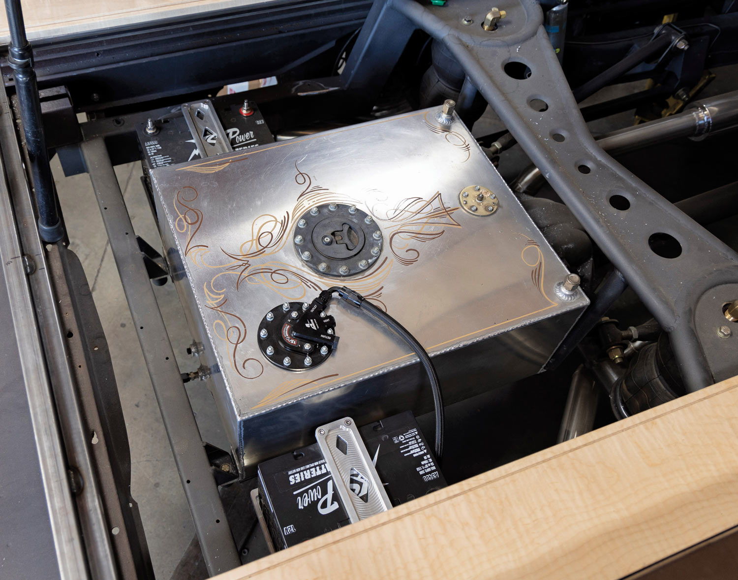
Images BY Taylor Kempkes
W

hen I started messing around with cars/trucks/bikes back in my formative years, the only things that mattered one bit to me about fuel systems were one, was it leaking too much; two, was the plastic filter clogged; and/or three, did I have enough gas to make it to the beach before sundown for a quick surf session? Typically, if it wasn’t running properly or I was running on fumes, I simply borrowed Mom’s Honda!

As the years progressed, I was forced to self-educate—from initially learning the proper procedure of freeing a stuck float with a hammer and slowly graduating to learning how to set the float in the first place, I became a vintage carburetion pro in my own mind. Fortunately, I was able to rely on others when it came to dealing with more advanced modern fuel systems … but still to this day, I prefer messing around with carbs (in my vehicles AND in my gut!).

So, when I acquired my ’48 Chevy, one of the first things I was asked if I was going to replace was the unique Edelbrock tunnel ram and 600-cfm four-barrel. My response was simple: Why? It runs and well, to be quite honest, so I’ll probably stick to the old mantra, “If it ain’t broke …” However, the same could not be said for the actual fuel delivery portion.

At first, I couldn’t figure out which was louder, the dual air compressors mounted to each side of the custom-fabbed aluminum fuel tank or the old-style fuel pump mounted to the framerail right beneath the cab. Turns out they were both equally as noisy, and seeing as Old Anvil Speed Shop will be replacing the entire ride control setup with Air Lift’s 3H/3P and FLO Air tank systems, that meant the fuel pump, which was actually plumbed in with the corresponding filter incorrectly, would be performing solo … until Paul, once again, had other things to say about that!

As was the case with the exhaust system, Paul was not about to facilitate Old Anvil’s brand-new All Access bed floor kit just to see—and hear—an old, outdated external fuel pump with its huge, antiquated filter nestled in with all the new components. “We’ve used Aeromotive on almost all of our builds,” he says. “They’re simple, universal to install in many applications, have never let us down … and … they’re super quiet!”

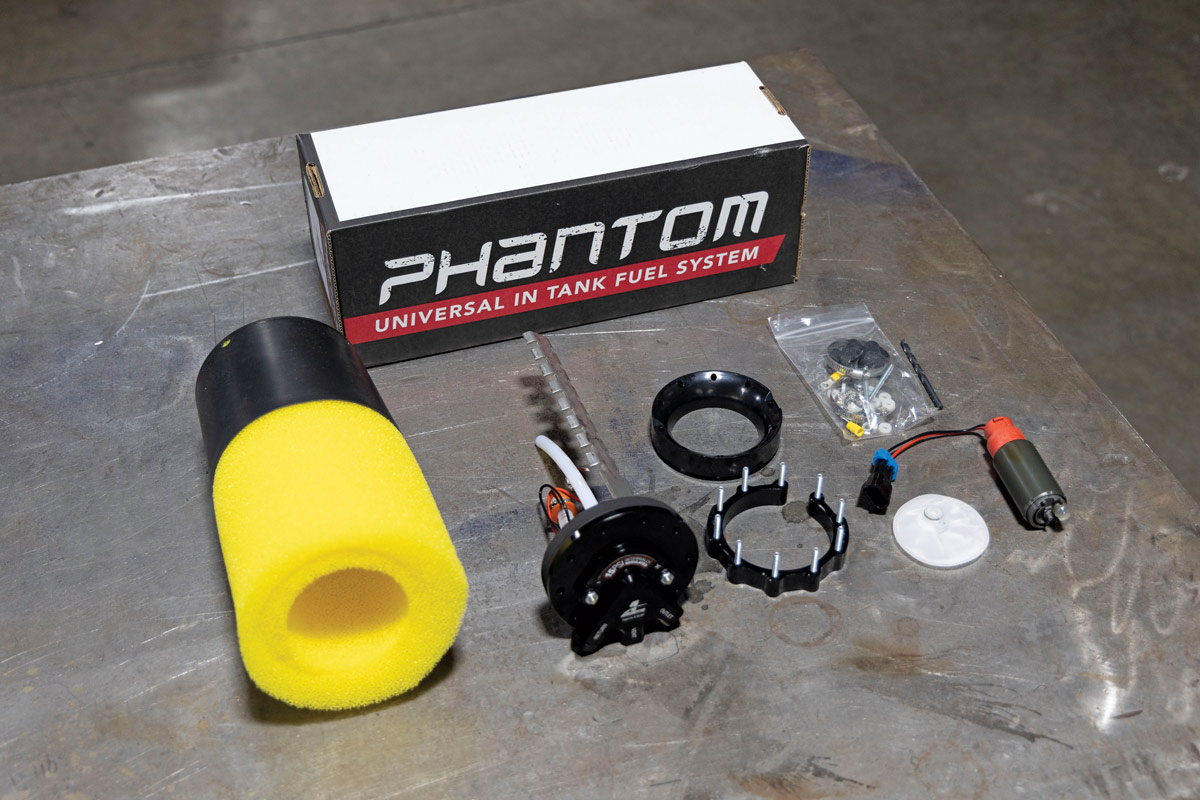
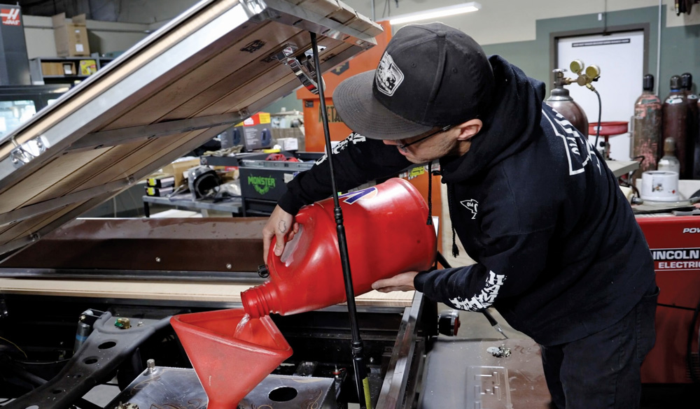
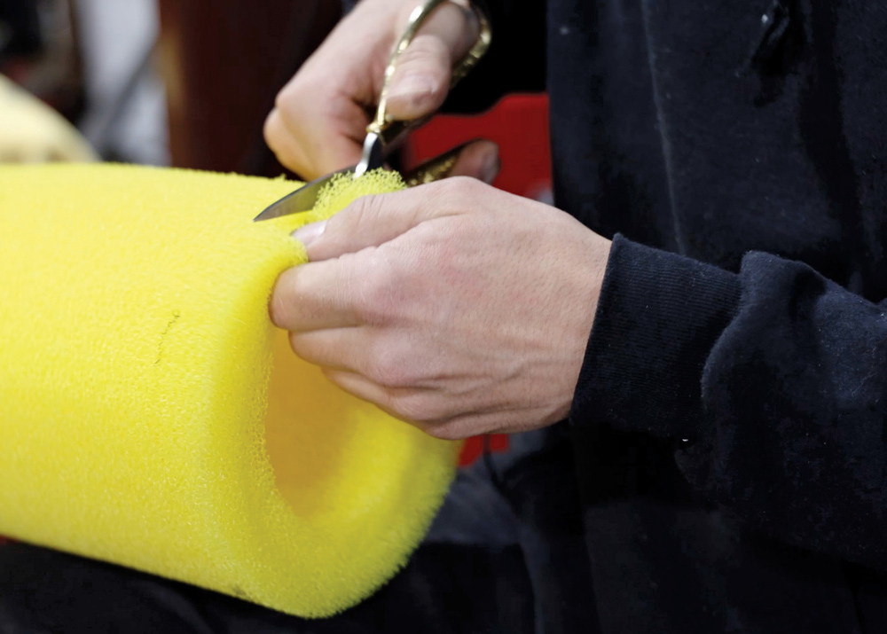
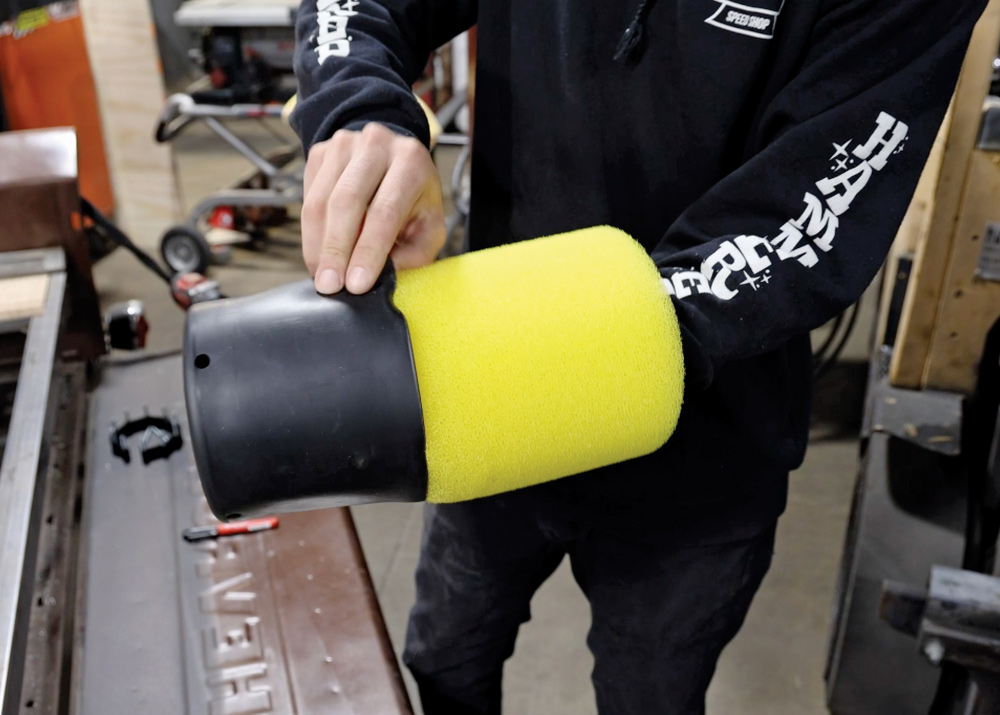
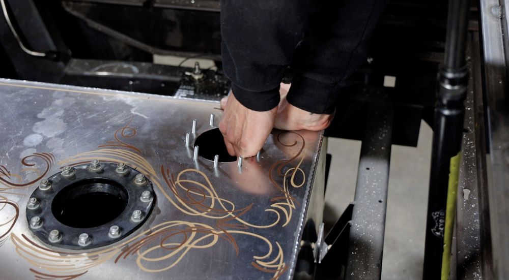
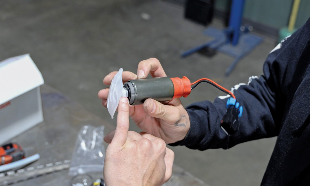
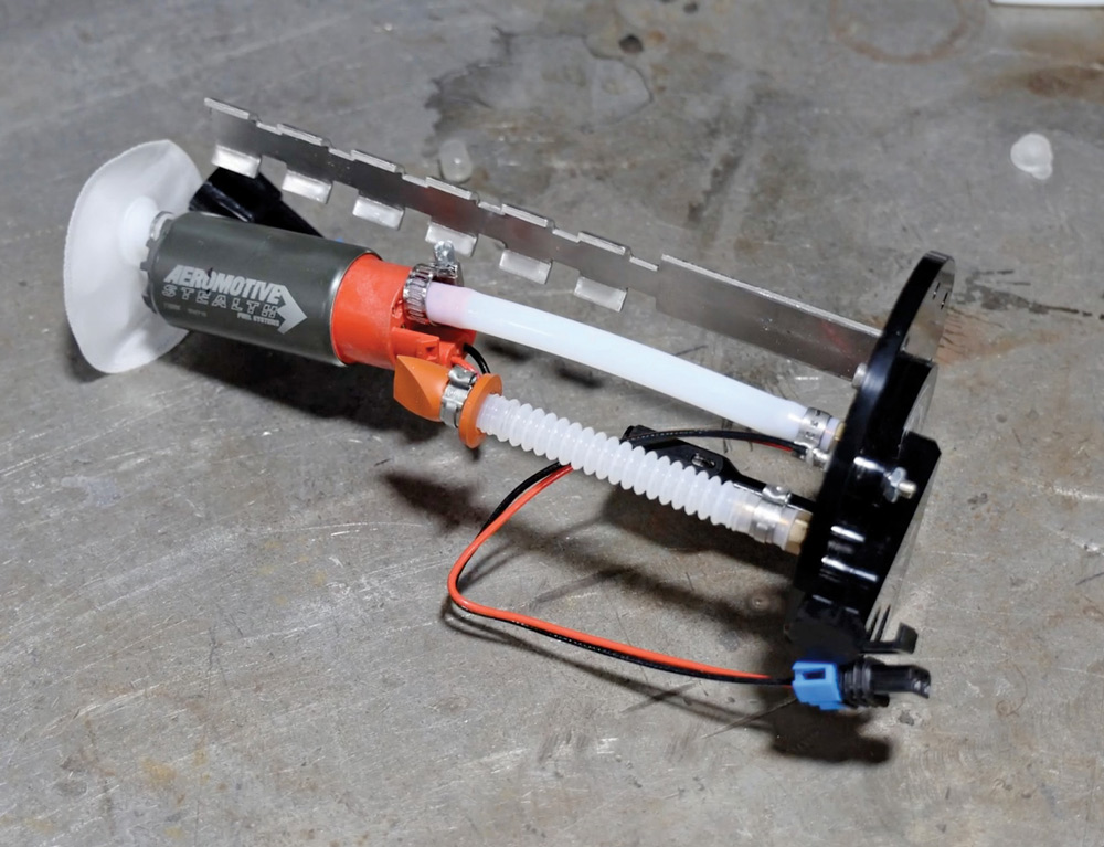
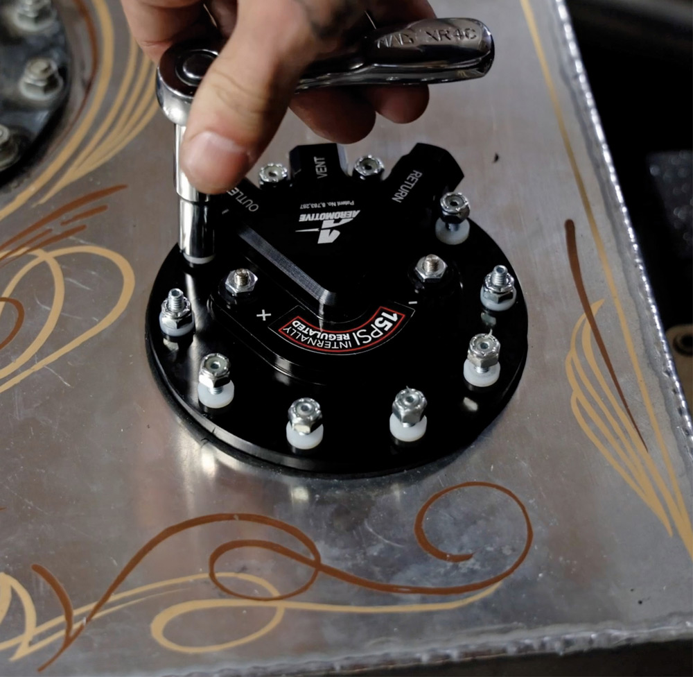
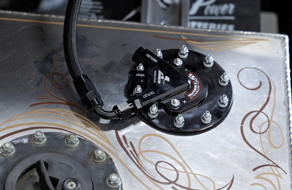
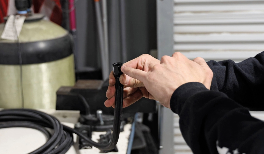
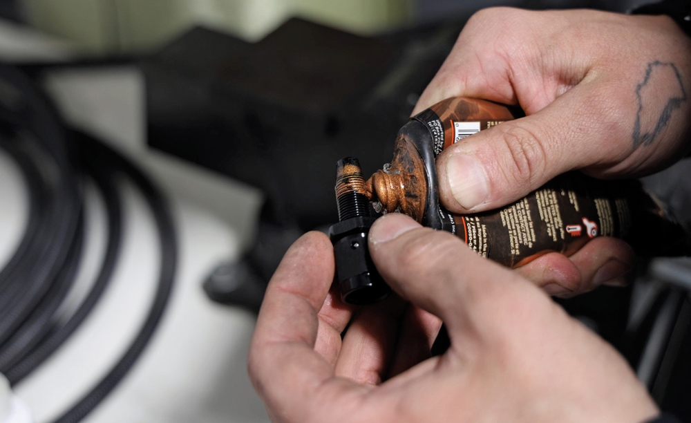
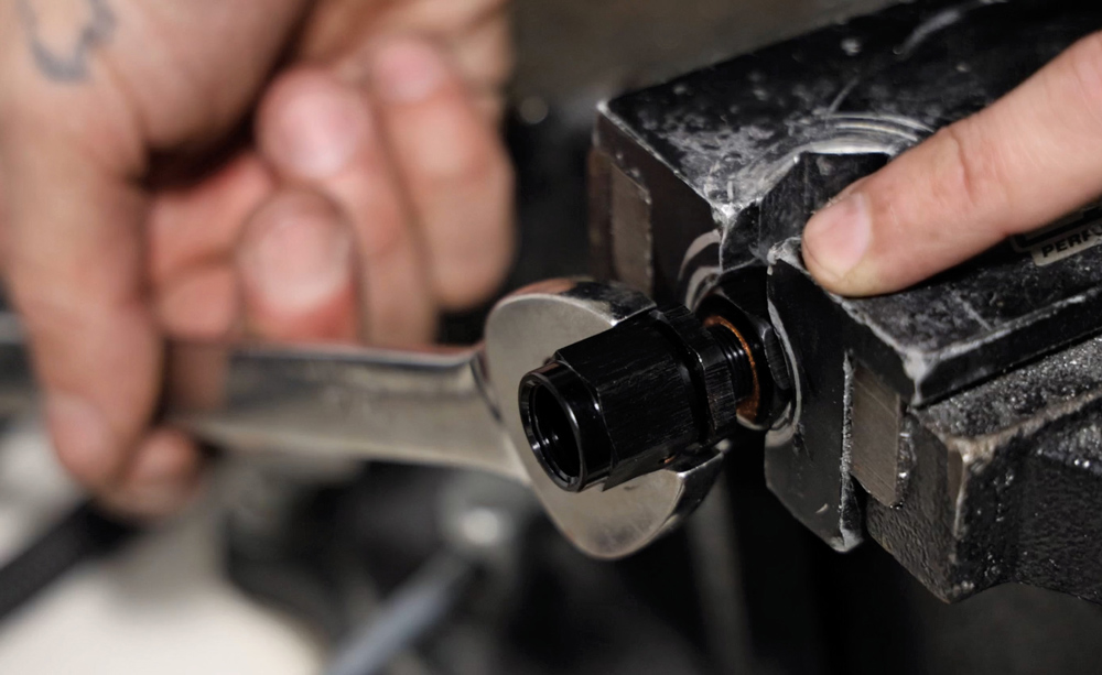
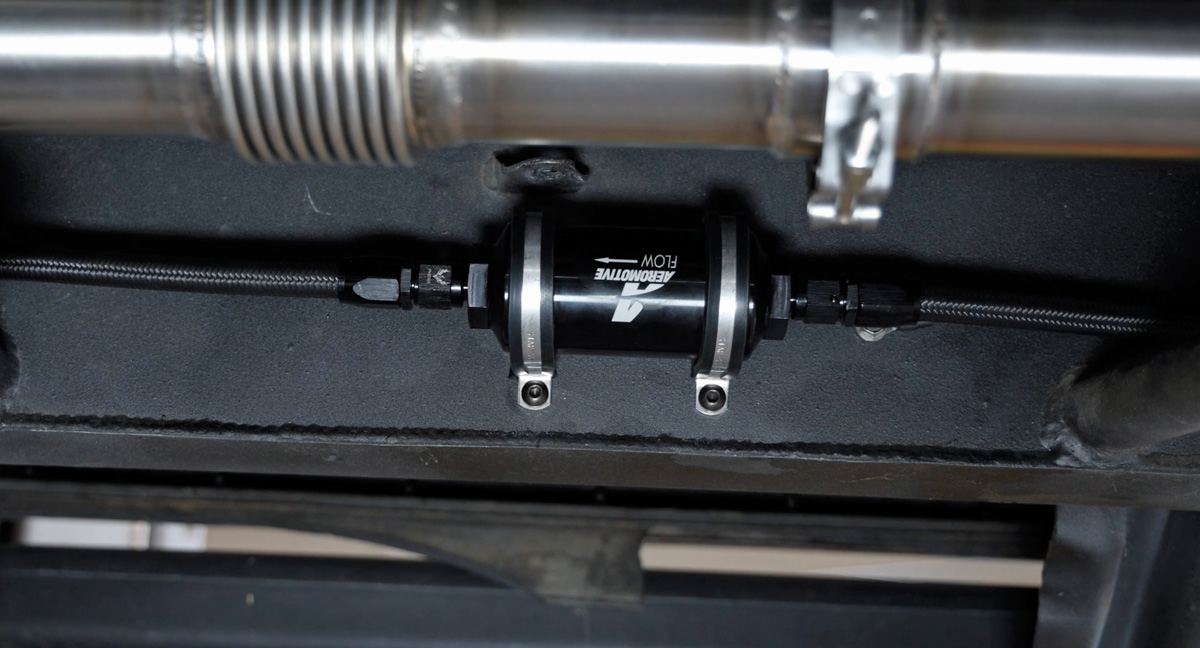
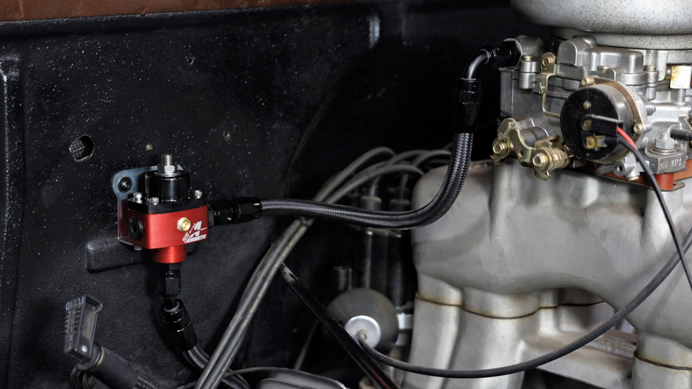
Ultimately, we selected Aeromotive’s Carb Returnless Phantom 325 (PN 18201) combined with their SS-Series ORB-6 Carb Regulator (PN 13201) and AN-06 10-Micron filter kit (PN 12347), all of which Old Anvil plumbed in using black-braided stainless hose and Phenix black-anodized AN fittings. This system, ultimately, can’t be beat when it comes to efficiently delivering fuel to a so-called “antiquated carburetor” induction.

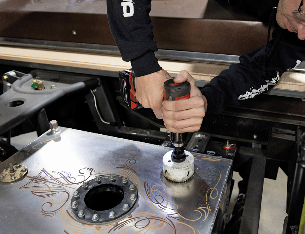
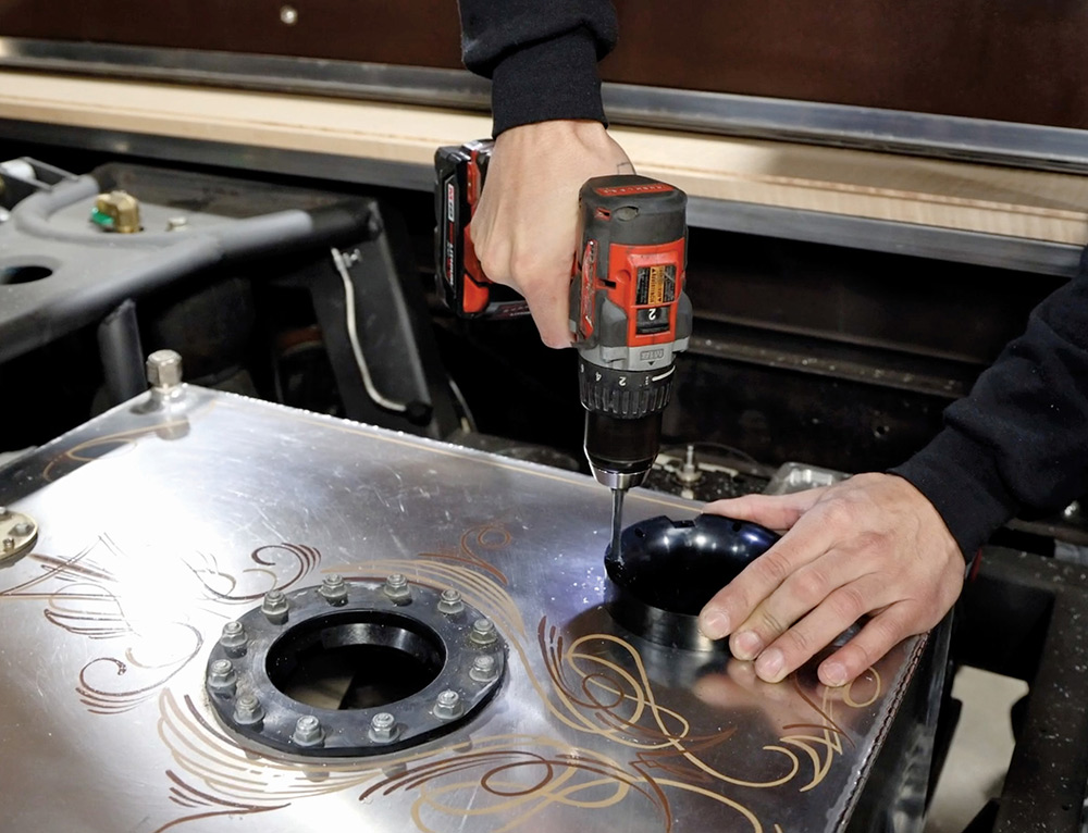
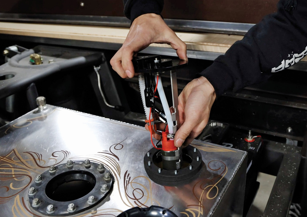
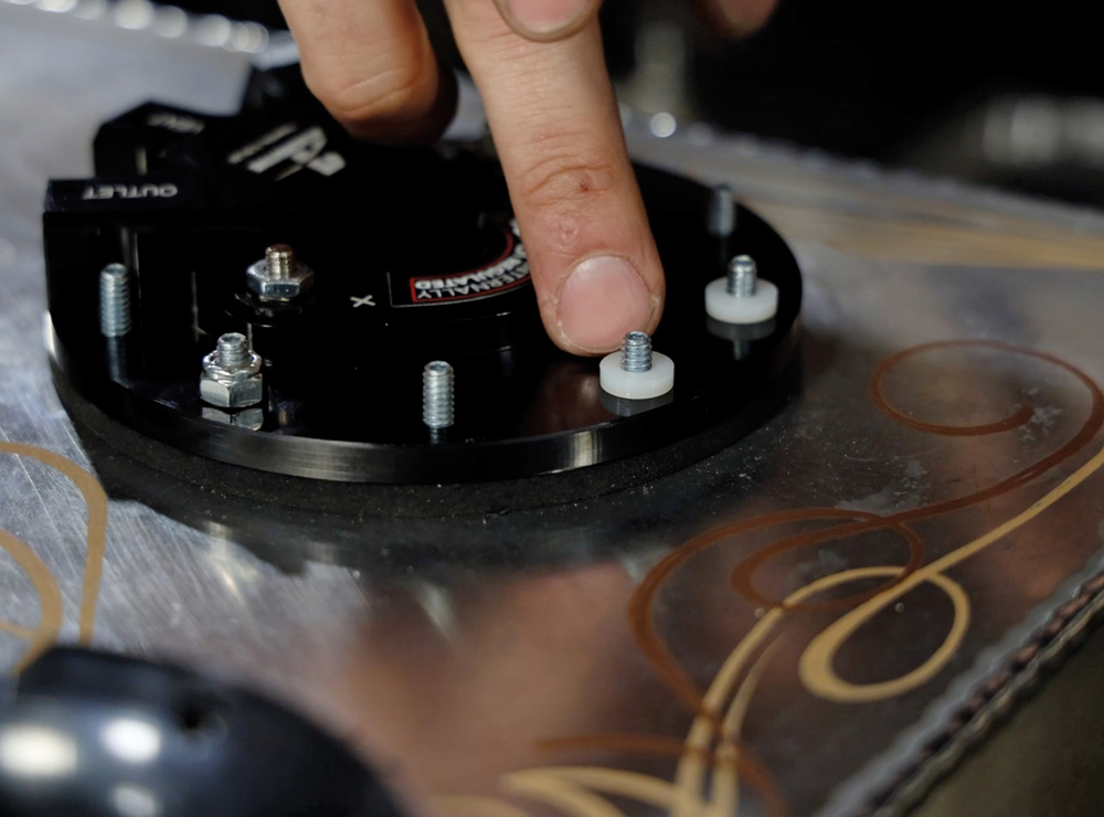
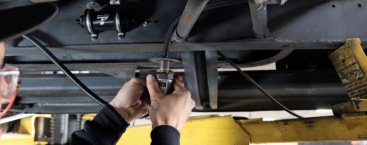
Fortunately, the existing aluminum fuel tank can remain in the system lineup—the new Stealth 325 15-psi (internally regulated) pump simply retrofits in and pressure reduced by the new regulator is mounted off the firewall, close to the carburetor; the serviceable filter is mounted inline off the framerail, in the vicinity of the prior components we’re replacing. Like Paul said, a very simple yet fully modern system that even I can understand … and work with! In the event I ever decide to do the throttle-body EFI conversion, I’m that much further ahead of the game fuel delivery–wise!

parts from the Aeromotive’s Phantom 325 returnless in-tank pump system
1. We’re just going to forgo the “old” pump situation altogether (photo-wise), as it was just that: an old, noisy, externally mounted electric fuel pump that had done its due diligence and was ready for retirement. Instead, let’s focus on Aeromotive’s Phantom 325 returnless in-tank pump system for carbureted applications, shall we.
locating and providing a mounting point for the Phantom pump unit
using a drill on the Phantom pump
2-3. Old Anvil began the installation by locating and providing a mounting point for the Phantom pump unit. Using the pump’s retainer ring as a template, a 3-1/4-inch holesaw followed by a cordless drill do the “dirty work”—literally. With Aeromotive’s thick gasket, the Phantom pump will mount—and seal—to a ribbed OE tank just a well as it will onto our fuel cell.
flushing out debris
4. Of course, the resulting debris was flushed out completely before proceeding with the pump assembly and install.
cutting a foam baffle
foam baffle testing a tanks depth
5-6. Next, after the newly cut holes were cleaned and deburred, the tank’s depth was measured so we could size the foam baffle and later establish the overall height of the pump system.
pump’s retainer ring and plastic installation ring installed
foam baffle installation
7-8. Before dropping the foam baffle and bladder into the tank, the pump’s retainer ring and plastic installation ring were installed so as to have a means in which to secure the two!
installation of the strainer/filter
using a tape measure on a strainer/filter
9-10. Now the pump assembly process begins, starting with the installation of the strainer/filter onto the end of the pump before it can be measured with the hanger assembly itself to achieve that previously determined in-tank depth …
excess material being trimmed off
11. … the excess material is simply trimmed off (bandsaw/cutoff wheel for the pump bracket; hose cutters for the tubing).
assembled pump system
12. The assembled pump system, prior to being prepped for installation (pump secured to the bracket; wiring attached and secured).
complete pump system being dropped in the tank
13. With the installation ring replaced with the provided foam mounting gasket, the complete pump system can be dropped in the tank.
nylon washers
two Nylocs that were hand threaded onto two mounting ring studs
14-15. To hold the pump system in place initially, as well as to help compress the gasket, two Nylocs are hand threaded onto two mounting ring studs—nylon washers are used beneath the 10-24 Nylocs.
pump system secured in place
fuel supply portion
16-17. With the pump system secured in place, the installation moves on with the fuel supply portion. (Once the bed floor assembly is complete, we’ll install a rollover valve/vent.)
Aeromotive billet 10-micron fuel filter being mounted
18. The Aeromotive billet 10-micron fuel filter is mounted in the same location as the old external fuel pump; the black stainless braided fuel line is cut to fit, allowing room for the -6 AN fittings.
hose end collar being installed onto the hose
end of the hose is flush inside the top of the fitting
19-20. The fitting process can be a bit tedious, especially if you’re not accustomed to the procedure. First, the hose end collar is installed onto the hose (counterclockwise) so that the end of the hose is flush inside the top of the fitting.
female AN portion is treated to a bit of antiseize before being installed
wrench tightening a bolt
21-22. To complete the connection, the female AN portion is treated to a bit of antiseize before being installed into the hose collar. And it should go without saying: avoiding fuel delivery leaks is reliant upon the “successful” assembly of your fittings … get them right/tight!
completed first section of the plumbing
23. That completes the first section of the plumbing—now let’s finish it off into the engine compartment.
Aeromotive’s SS Series ORB-6 carb regulator
24. To dial the pressure down, we used Aeromotive’s SS Series ORB-6 carb regulator, which was mounted on the firewall, in close proximity to the Edelbrock 600-cfm carb (which was retrofit with a -6 AN inlet fitting replacing the old barbed inlet), and wrapped up the plumbing accordingly.
SOURCES