CTP Tech
InTheGarageMedia.com
Doubling down on double-inverted flares
Plumbing a Brake System the Original Way
BY Ryan MansonImages BY THE AUTHOR
P

lumbing the brake system of a classic truck doesn’t require the use of exotic materials or methods and shouldn’t be a job beyond the ability of most DIYers. A few simple tools and a little bit of patience can yield some very nice results. We’ve covered the fancier side of things, installing a full stainless steel AN system on another C10 build we’re working on, but this time we’re going to shift our focus to the more common materials and techniques found at the local parts house.

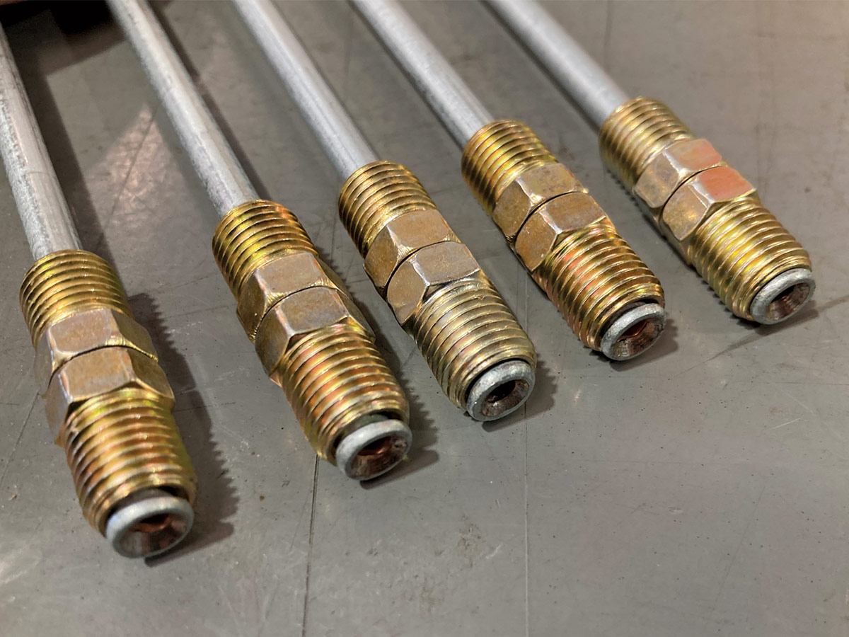
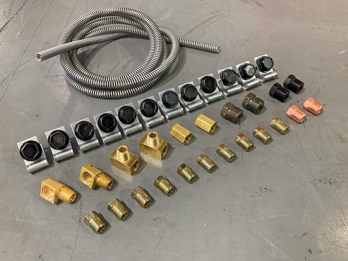
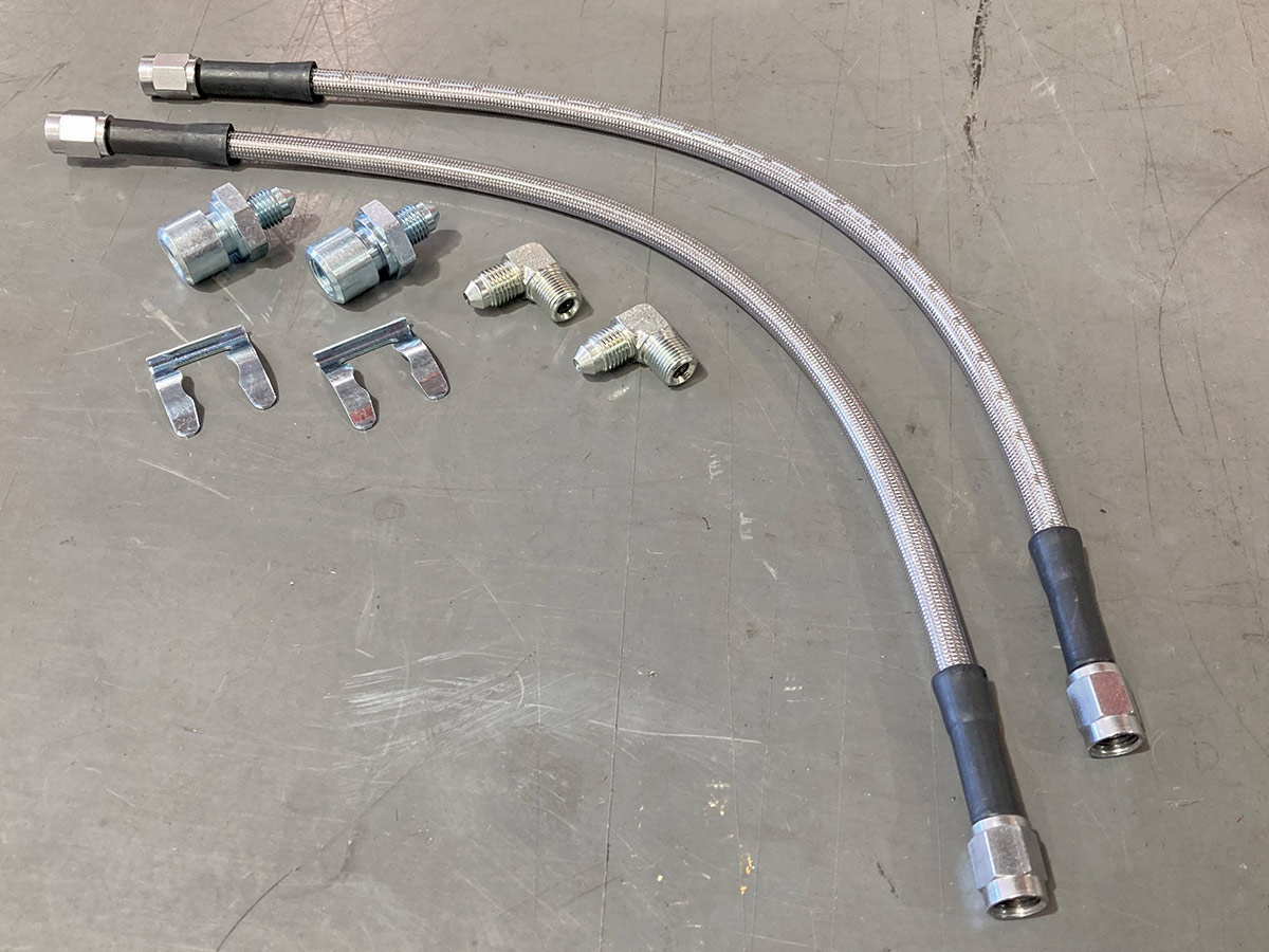
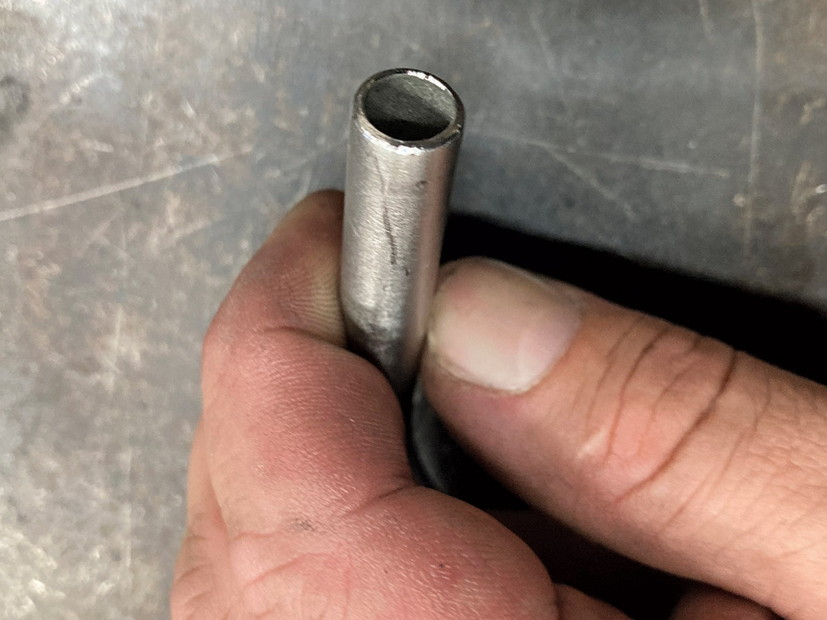
If you’re purchasing your brake lines and fittings from the parts supplier around the corner, chances are you’re going to be presented with few options. Brake line material will most likely be either steel or nickel/copper with fittings of the double-inverted flare variety. Both materials are fairly easy to work with, provide excellent resistance to corrosion, deterioration, and damage, and can be worked using standard hand tools. Steel brake lines, most of which are constructed using a combination of steel and copper with a protective zinc coating, have been the de facto standard since most of these trucks were new. More function than form, steel brake lines are easy to work with and provide excellent performance but lack the impressive appearance that stainless lines exhibit. Steel is also more affordable than stainless lines and components by a factor of about half. The use of nickel/copper lines, commonly referred to as NiCopp, has found an increase in popularity amongst both OEs and aftermarket companies due to its ease of workability (bending and flaring) and corrosion resistance. This makes it a popular material for the home builder as it bends easily using hand tools (or your bare hands!) and when properly treated, forms a double-inverted flare without splitting, cracking, or deforming without the use of a high-end flaring tool.

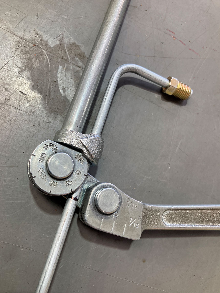
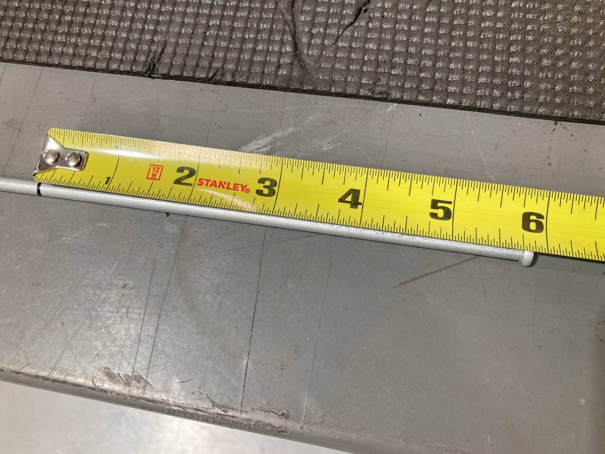
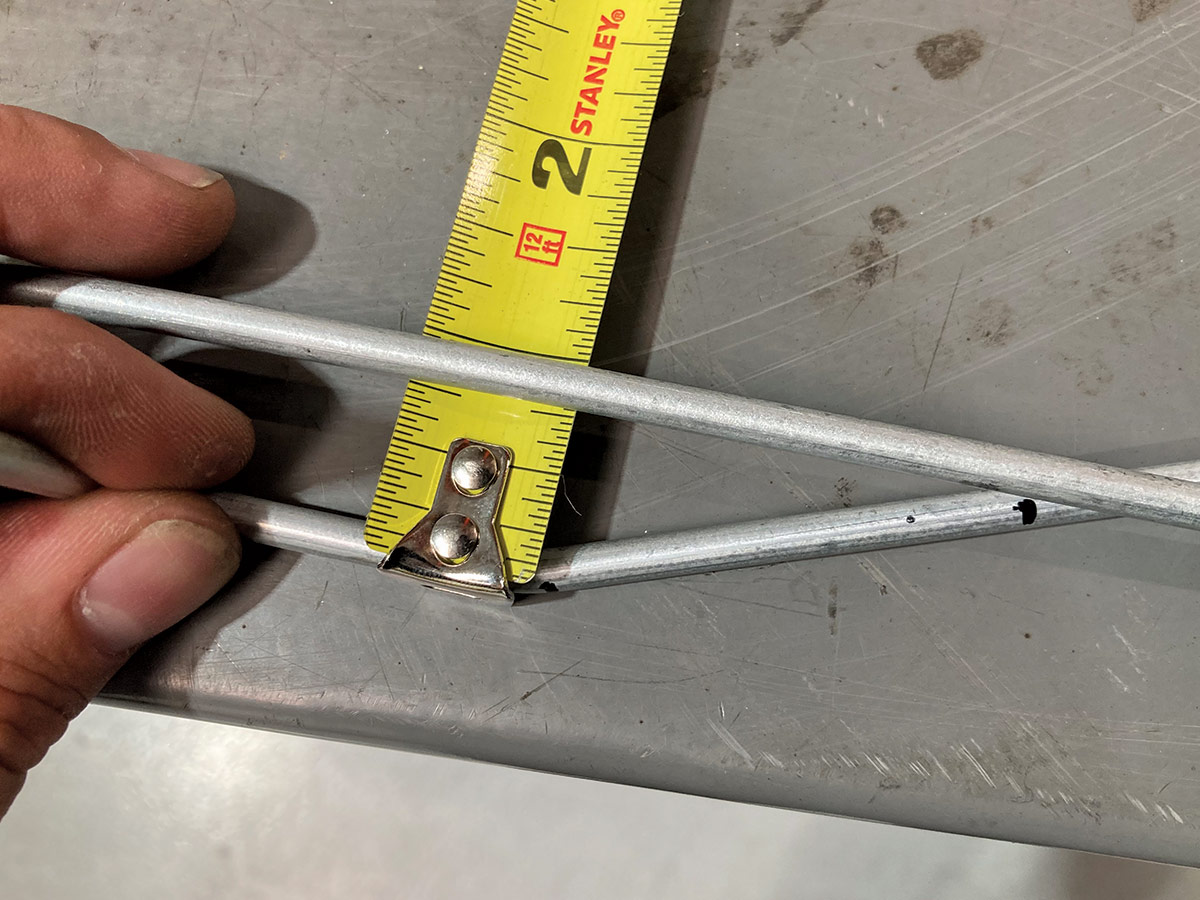
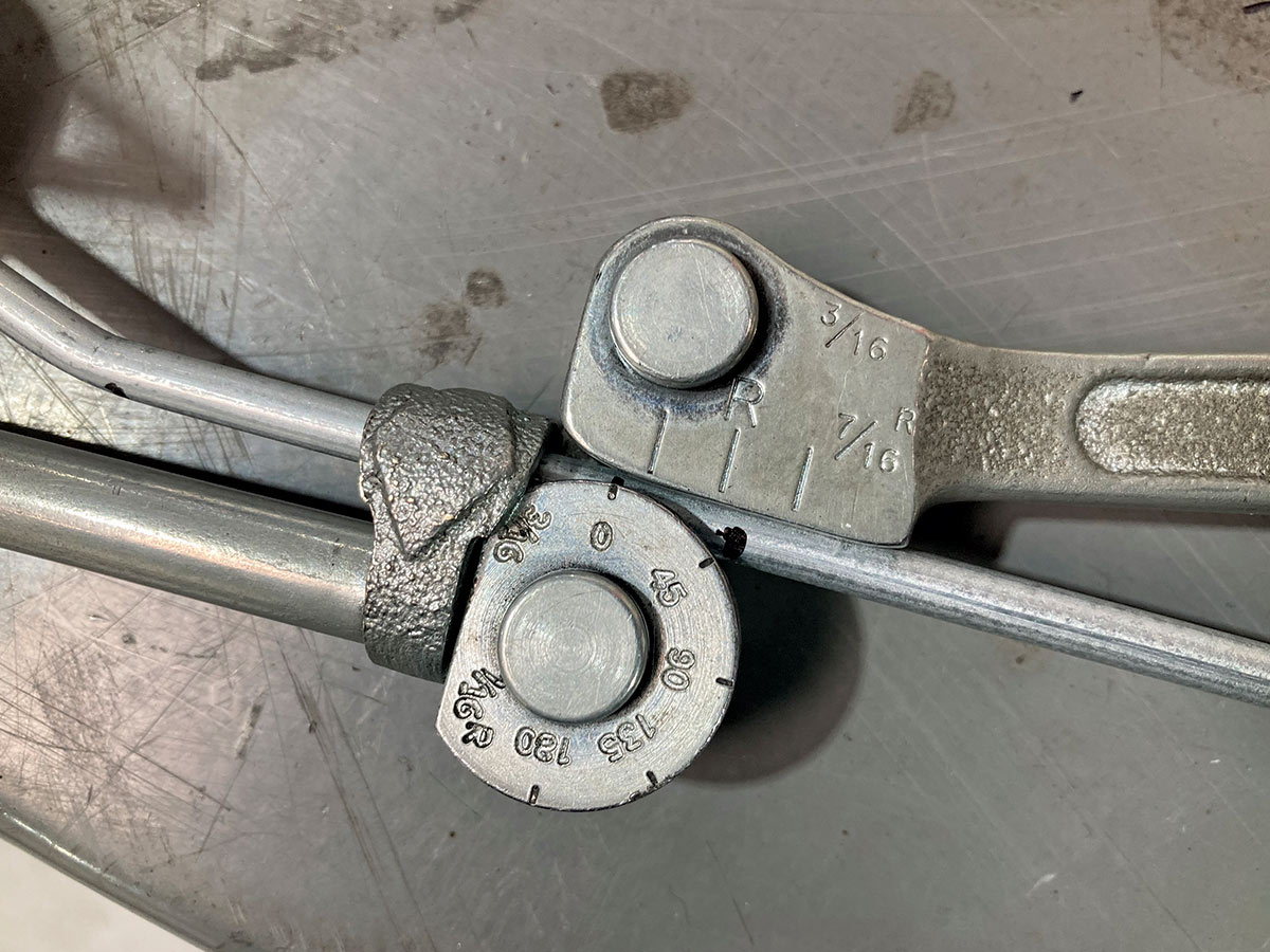
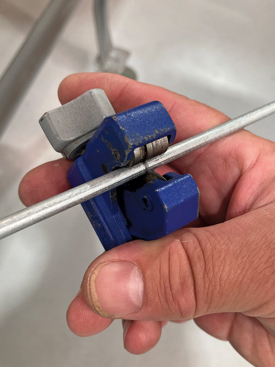
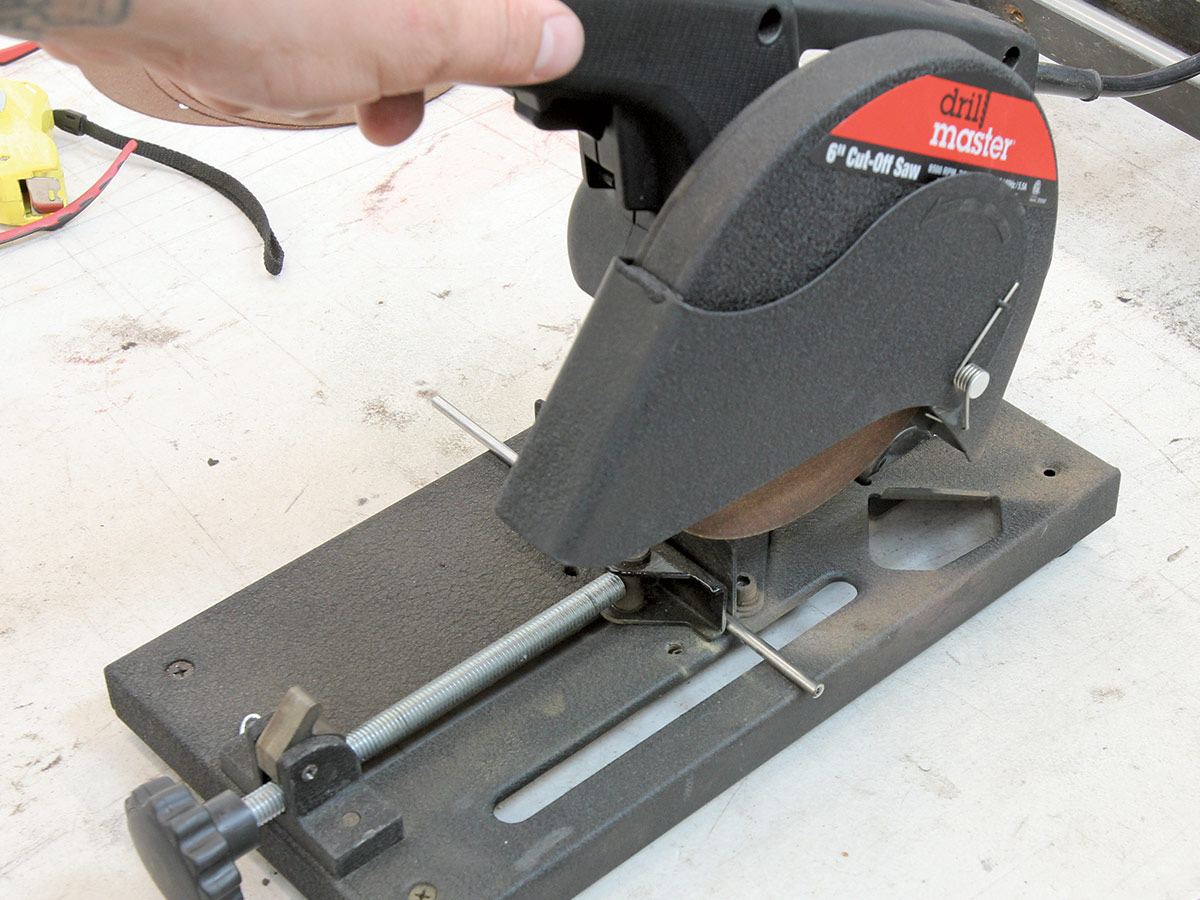
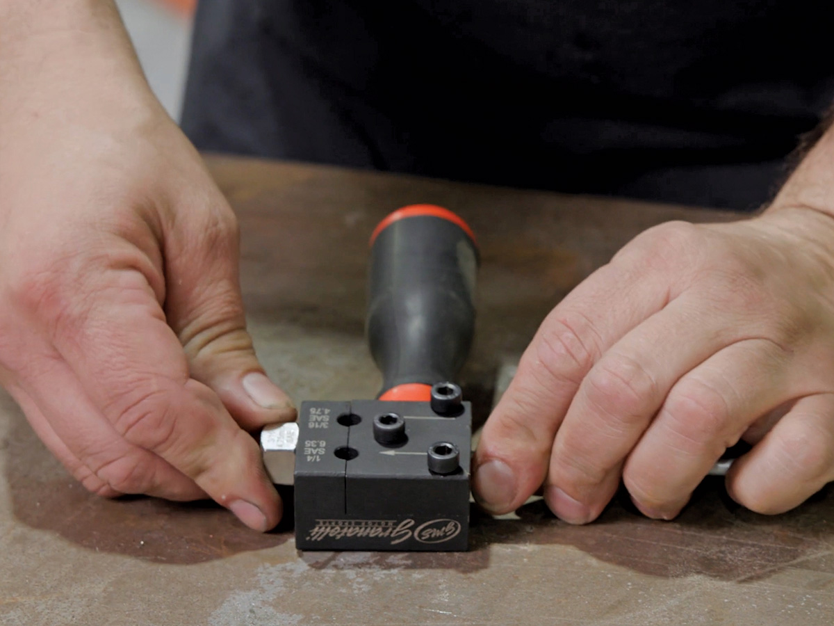
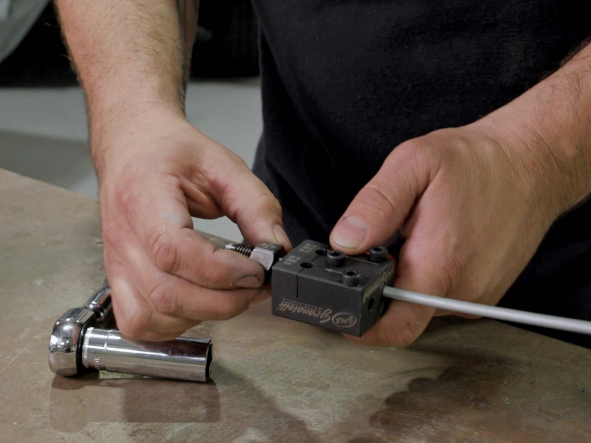
While a drawer full of tools makes for easy fabrication of a pro-level plumbing system, it’s not necessary. A decent bender and a good flaring tool can yield some surprisingly good results, both of which can be purchased over the counter from most auto parts shops. Personally, I prefer to make tight bends as opposed to sweeping, over-the-knee curves, so my bender-of-choice is one I scored at a swap meet that features a radius of 7/16 inch and is used for 3/16-inch lines only. Some jobs require larger radii bends, so it’s good to have a couple options when it comes to benders, but it’s not necessary.

Making consistent double-inverted flares can be challenging in harder material (stainless) even with a good tool. Those cheap wing-nut, handheld versions, forget it! Steel is easier to work with thanks to its part-copper construction, with NiCopp being even easier due to its softer makeup. Though these materials are easier to work with, it still pays to use a quality flaring tool. Consistency is key when it comes to completing the first and second operation necessary to form a double-inverted flare. If the first flaring operation is inconsistent, the second operation where the flare is folded back over itself will be affected negatively, resulting in an ugly flare in the least and a leaking junction at the worst. Suffice it to say, that careful prepwork is also key, ensuring that the tubing end to be flared is cut square and properly deburred beforehand.

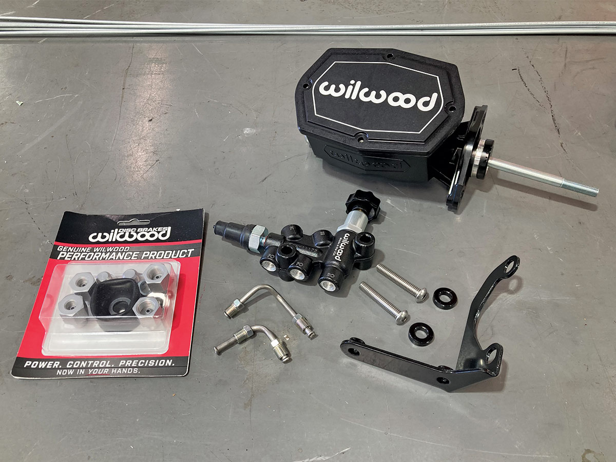
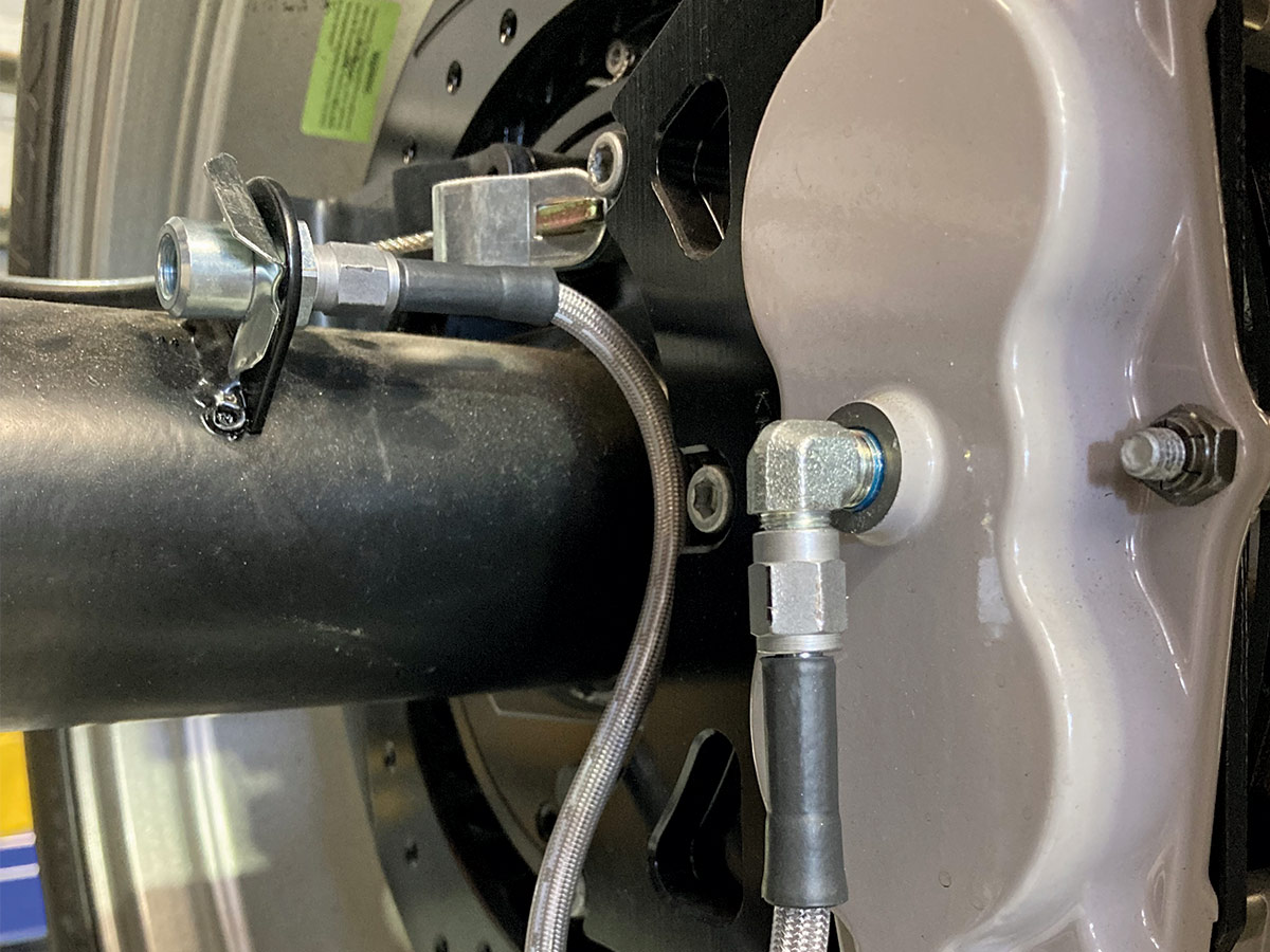
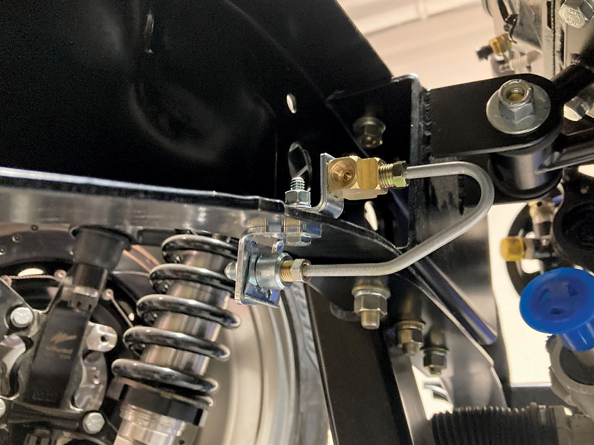
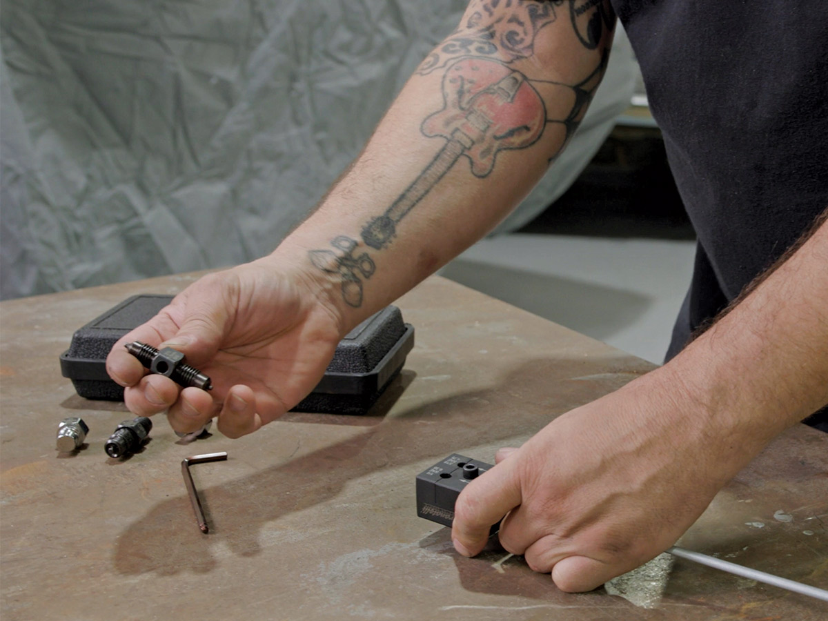
Fabricating a full brake system using a handful of straight sections of tubing can be a daunting task at first glance and might result in taking a second look at those pre-bent line kits that many manufacturers offer. But unless you’re restoring a truck with stock components, most of the pre-bent kits won’t provide a solution for every individual brake line. Our ’64 C10 build, for example, features a Chris Alston’s Chassiworks KP Components rear frame clip, Scott’s Hotrods ’N Customs IFS, and a Wilwood master cylinder and four-corner disc brake kit. All these custom modifications negate the possibility of using a pre-bent brake line kit based off stock C10 specs due to the drastic difference in chassis features.

Plumbing a brake system from scratch is a labor-intensive project, but not beyond the scope of most hands-on–type truck builders. A weekend spent bending and flaring lines can result in a very attractive system that looks as well as it functions. With the proper tools and a few good tips, anyone can plumb their project with ease!

five steel brake lines
1. A handful of 4-foot sections of 3/16-inch steel brake lines will provide the foundation of our brake system.
various flare nuts and clamps
2. A variety of clamps, flare nuts, and fittings, courtesy of Classic Performance Products (CPP), are also on hand and will be used as needed.
Wilwood Compact Tandem master cylinder
3. Boosting the pedal pressure to that with which the brake system requires will be handled by a Wilwood Compact Tandem master cylinder featuring a bore size of 15/16 inch (PN 261-14962-BK), recommended by the guys at Wilwood as a mate to the Wilwood calipers resting at all four corners of the truck. An adjustable proportioning valve is included as part of the master cylinder kit and is an important addition due to most pickup’s uneven weight distribution and subsequent brake bias. This allows the brake system to be adjusted for a more even brake bias front-to-rear to prevent the rear brakes from locking up before the front.
Wilwood master cylinder
4. With the Wilwood master cylinder assembly secured to the firewall in the stock location, brake line fabrication can commence.
yellow measuring tape measuring prop valve
5. The outlets for both the front and rear ports are inline on the bottom of the prop valve, which means the outlet for the front brakes is further from the firewall. We’ll start with the rear outlet first as that will be the “outside” line when it comes to how they land on the firewall.
brake line fabrication
6. The first bend was created as close to the end of the line as possible by placing the bender against the tube nut and forming a 90-degree bend. This will direct the line back toward the firewall. Using the measurement we just took, the line has been marked to suit and the brake line bender placed so that the final bend will yield the length required to land the line against the firewall while clearing the steering column hole in the firewall. Note that we’re going to start the bend 7/16 inch back from the marked line, taking the radius of the bender into consideration.
yellow measuring tape measuring prop valve
7. Our first couple bends are a success and measure exactly as expected.
Making our way down the firewall requires a bit<br />
of dodging and weaving, but eventually we make<br />
our way rearward.
8. Making our way down the firewall requires a bit of dodging and weaving, but eventually we make our way rearward.
4 foot long brake line installed using clamps
9. We reach the end of the 4-foot line near the back of the cab, so a union is installed and a new section of line begun. Note the use of combination line clamps keeping the brake line in place. The larger end of the clamp will support the hard line for the C10’s fuel system.
The second section of the rear line terminates at a bulkhead fitting in the rear crossmember
10. The second section of the rear line terminates at a bulkhead fitting in the rear crossmember.
Unlike the double flares used so far, the bulkhead<br />
fitting required a 37-degree AN flare, nut, and<br />
sleeve to be used.
11. Unlike the double flares used so far, the bulkhead fitting required a 37-degree AN flare, nut, and sleeve to be used.
two stainless brake hoses
flex lines installed at the calipers allow them to be<br />
removed for pad placement
12-13. A pair of stainless braided brake hoses from CPP (PN 220-7056) will be used on the rearend to mate the Wilwood brake calipers to the hard lines that will span the length of the rearend housing. Use of flex lines at the calipers allow them to be removed for pad placement without disrupting the brake’s sealed hydraulic system.
CPP (PN TE06)
14. The left and right hard lines will meet in the middle, at this Tee fitting from CPP (PN TE06) that will mount on top of the rearend housing.
yellow measuring tape measuring brake line
15. Each line will feature a handful of bends to route the line neatly across the rearend. While these could be done freehand, I prefer to do things more methodically, in an effort to keep the two sides fairly symmetrical. Here, the first bend is marked at a predetermined location. This will be mimicked on the opposite side.
yellow measuring tape measuring brake line with 45 degree bend
16. This first bend will actually consist of two 45-degree bends to get the line tight against the housing from the raised brake line tab. The distance from the center of the tab to the housing is 3/4 inch, so the “z” feature needs to reflect this. A section of spare hard line is used to mark the line, acting as a square of sorts.
3/4-inch length marked on brake line
17. Taking into consideration the 7/16-inch radius of our bender, an additional mark is made that much shorter than the 3/4-inch length we’re after.
The bender is then lined up with the shorter<br />
mark so that the radius of the bend is accounted for<br />
in the total distance.
18. The bender is then lined up with the shorter mark so that the radius of the bend is accounted for in the total distance.
Once completed, we’ve successfully created a 3/4-inch jog in the line. This process can then be repeated on the opposite side.
19. Once completed, we’ve successfully created a 3/4-inch jog in the line. This process can then be repeated on the opposite side.
two brake lines with incorrect bends

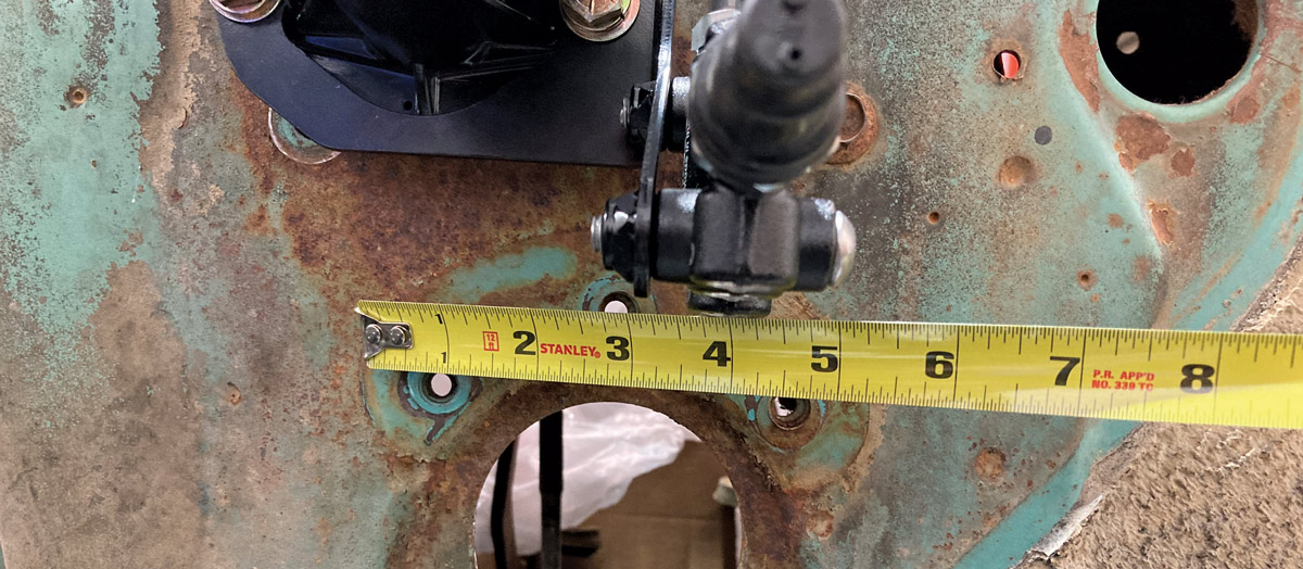
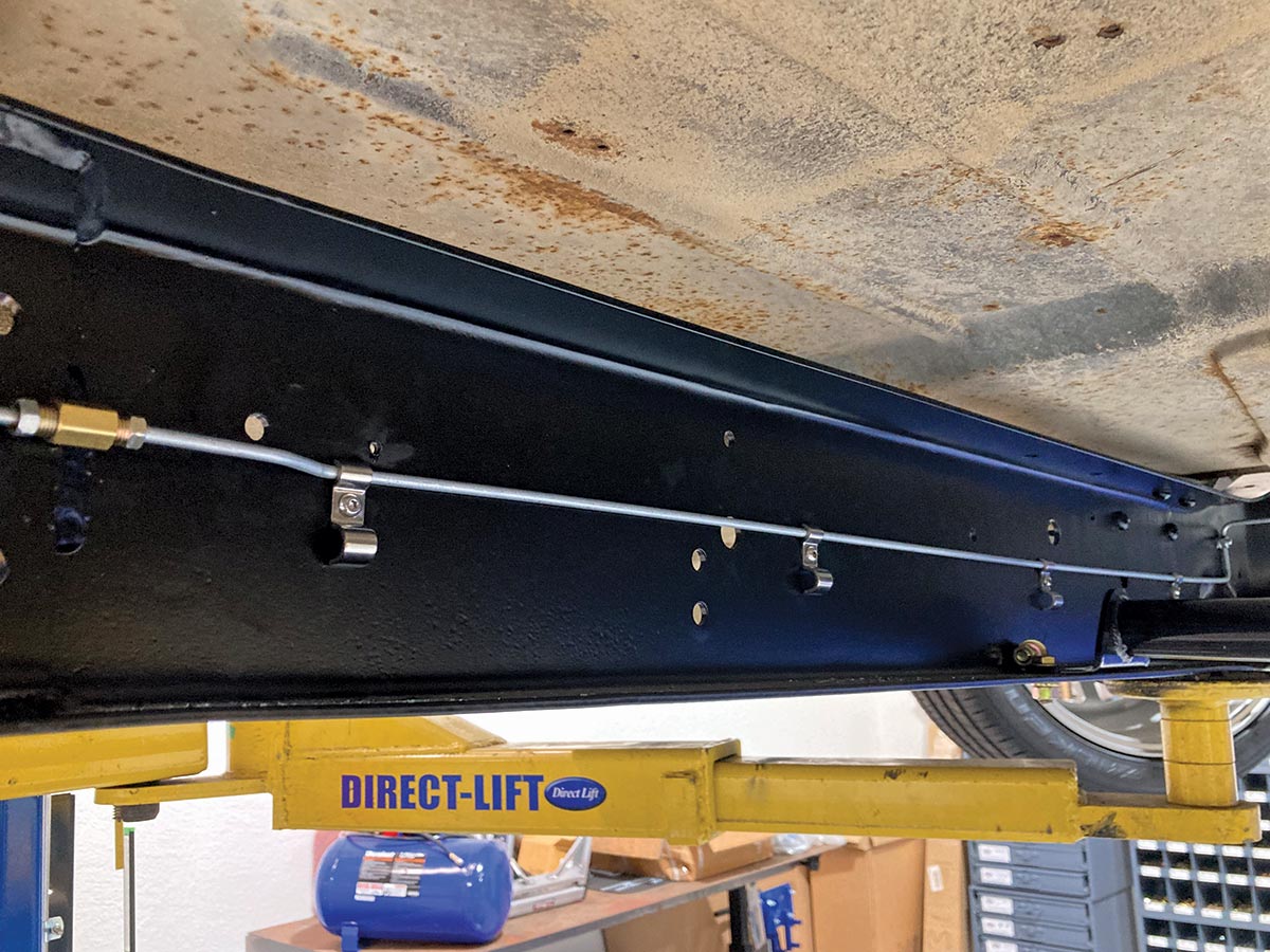
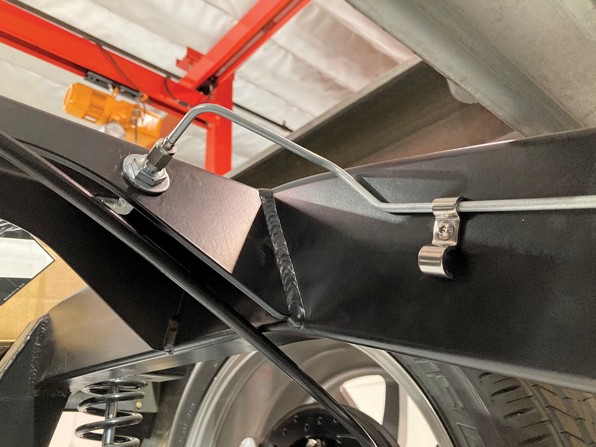
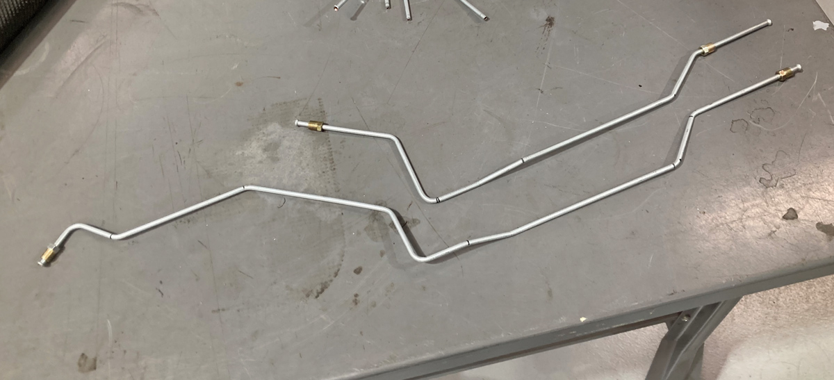
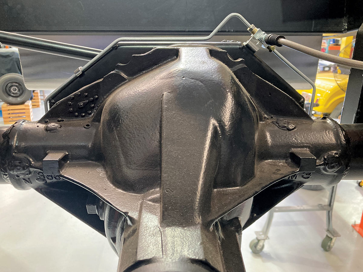
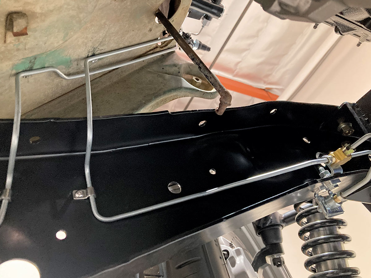
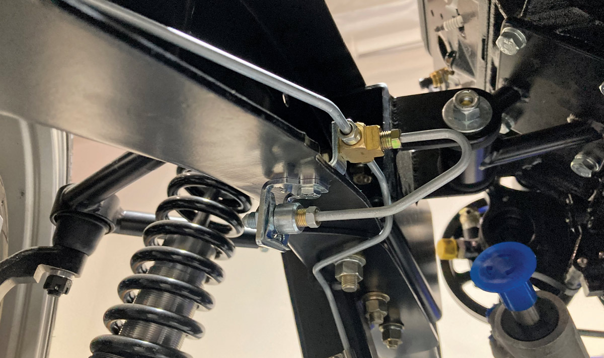
20. Here’s the finished hard lines for the rearend. Note the similarities of the brake tab side (right). Bending mistakes happen, but we can make lemonade from our lemons by setting an incorrectly bent line aside to either be used later at a different location or as a template for a similar bend. That pile of pre-bent hard lines is a small sample of “whoopsies” that I keep in my brake hardware drawer for situations such as these. Sometimes it’s easier to grab a section of pre-bent line, modify to suit, and then translate that to the larger line being fabricated.

Both hard lines terminate at the aforementioned Tee fitting, mated to another CPP stainless braided hose.
21. Both hard lines terminate at the aforementioned Tee fitting, mated to another CPP stainless braided hose.
That hose connects to the bulkhead fitting on the frame, effectively completing the rear brake line circuit.
22. That hose connects to the bulkhead fitting on the frame, effectively completing the rear brake line circuit.
two brake lines with bends being installed
23. The first line is the easiest, getting the second to match can be a challenge, especially when dealing with a long, straight section of hard line. Note that the first bend on both lines is the same, while the length between the first and second is exceptionally longer on the front line.
A double line clamp holding brake lines in place
24. The goal is to have both lines run parallel and symmetrical to one another when possible. A double line clamp ensures things remain in place.
single brake line will run from the master cylinder to another Tee fitting, where it will then split between the left and the right side of the chassis
25. A single brake line will run from the master cylinder to another Tee fitting, where it will then split between the left and the right side of the chassis. A brake tab fitting will secure the junction between the hard line and each braided hose. Here, the driver side hard line from the Tee to the brake tab has been bent to shape and installed.
passenger side installed with brake lines
26. The passenger side is arranged in a similar manner, with the line held fast against the crossmember via more stainless steel line clamps.
end of the front line from the master cylinder to the Tee
27. The business end of the front line from the master cylinder to the Tee …
Tee junction
28. … and the final Tee junction.
Functional Flaring
Flaring brake lines isn’t complicated, but it does require decent tooling. Thankfully, there are a number of tools available on the market, depending on the type and location of the flare.
a tube cutter being used on a brake line
1. A clean, square cut is important in creating a good flare in any tubing, regardless of the material or type of flare to be made. A small tubing cutter works great for softer materials like NiCopp …
small chop saw
2. … while harder material like stainless can be cut using a small chop saw.
tool used to deburr tubing
tubing being deburred
closeup of fingers holding tube to deburring tool
hand holding finished deburred tube
3-6. Regardless of the method used to cut the tubing, it will need to be deburred to ensure a good flare and this generic deburring tool, available from a number of sources, works great to deburr both the id and od of tubing up to 3/8 inch.
On-Vehicle Flaring Tool box
7. There are several great flaring tools on the market, but when it comes to double-flaring tubing on a vehicle, this compact, On-Vehicle Flaring Tool from Granatelli Motor Sports works great when space is at a premium.
hand using On-Vehicle Flaring Tool
8. Three steps are required to form an inverted flare using Granatelli’s tool. First, the tubing is inserted into the tool against a stop that sets the depth of the tubing.
the first flare is created using one side of the flaring die.
9. Next, the first flare is created using one side of the flaring die.
The die is then flipped around and reinstalled to create the inverted flare.
10. The die is then flipped around and reinstalled to create the inverted flare.
double inverted flare
11. The result is a flawless double inverted flare that can be made without removing the line from the vehicle, perfect for making repairs or modifying an existing brake line or for fabricating new lines without taking everything back apart.
SOURCES