Tech
Tech

 Images By The Author
hen it comes to worthwhile upgrades on the beloved 1988-98 Chevy, the rear brakes are one of the most overlooked—but most rewarding—places to start. Anyone familiar with these trucks knows the factory rear drums aren’t exactly confidence inspiring. Sure, you can tweak them, adjust them, clean them, and follow countless DIY videos on how to squeeze a little more life out of GM’s original setup. But eventually, the brake fade, uneven stopping, constant adjustments, and overall clunky feel make it clear: it’s time for something better.
A rear disc brake conversion may sound like a big step, but, in reality, it’s one of the easiest ways to improve consistency, braking power, and overall driveability. Rear discs mean less maintenance, cleaner operation, and far more predictable stopping—especially if your truck actually gets used the way these trucks were meant to be used. And, let’s face it, an iconic workhorse like the 1988-98 Chevy deserves modern braking performance, not 30-year-old drum technology. The real question becomes: who offers a complete rear disc kit that upgrades performance without adding unnecessary complications?
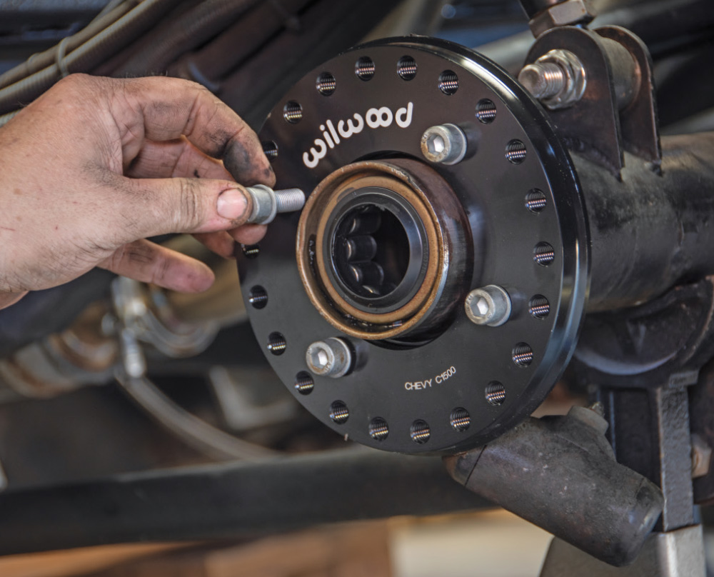
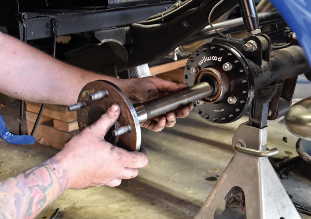
After more than two decades personally installing Wilwood systems on muscle cars, hot rods, and daily driven trucks, we were eager to see what they brought to the table for this platform. That’s when we came across the XRS calipers—a street-friendly evolution of the XRZ race calipers—built from forged aluminum, impressively stiff, and incredibly lightweight. We also made the necessary switch to their Compact Tandem Master Cylinder, which included the option to color-match the calipers. In this rear-brake conversion and master cylinder walkthrough, you’ll see how Wilwood managed to put together a clean, high-performance, and surprisingly simple rear disc kit—one you can absolutely install in your own garage, just like we did.


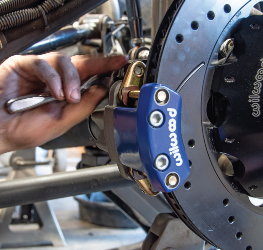
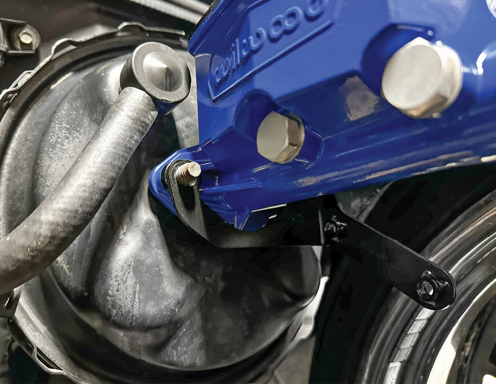
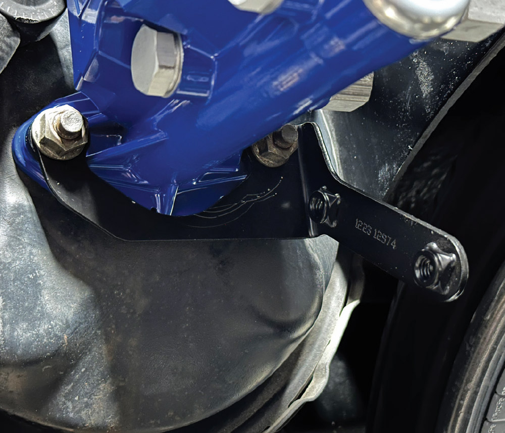
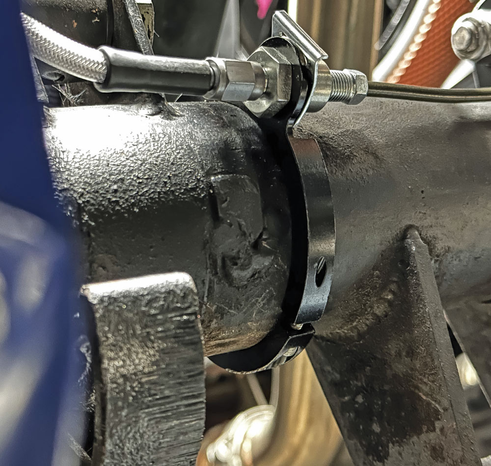
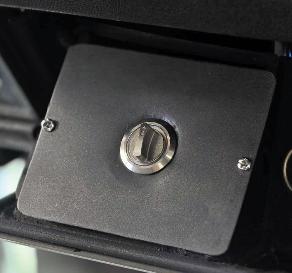
19. Install the e-brake anywhere you want it … literally. The adapter plate allows you to go all the way around. Loosely install with supplied hardware and center the caliper on the rotor with supplied shims. Once you are satisfied, take the mounting hardware off one by one and reinstall with red Loctite and supplied torque specs.

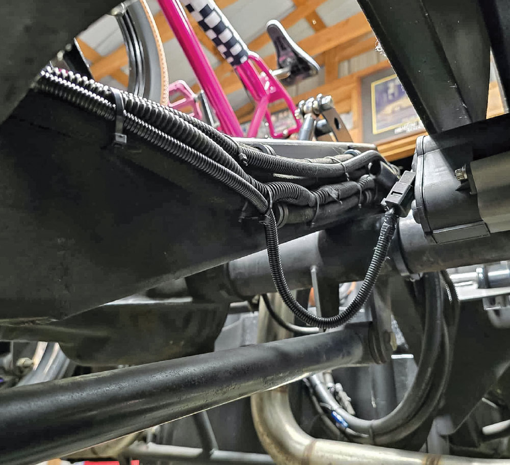
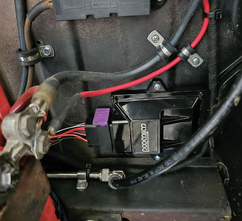

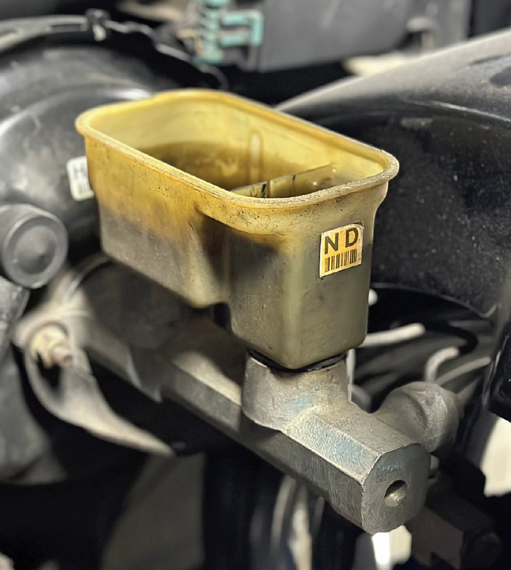
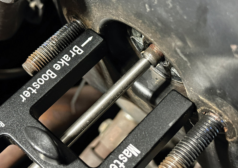
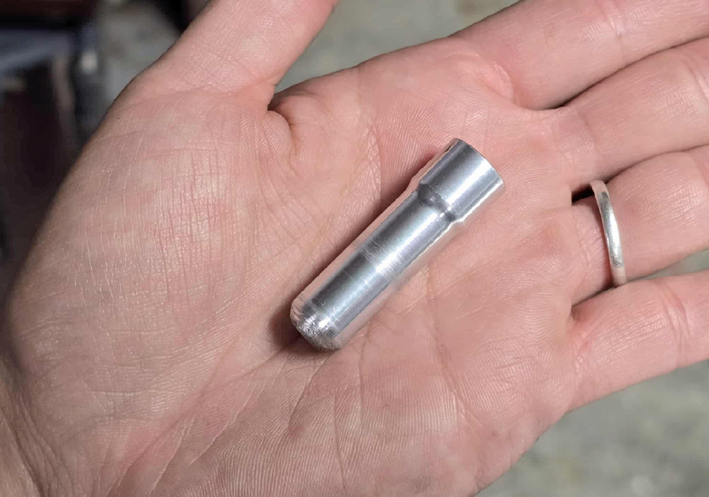
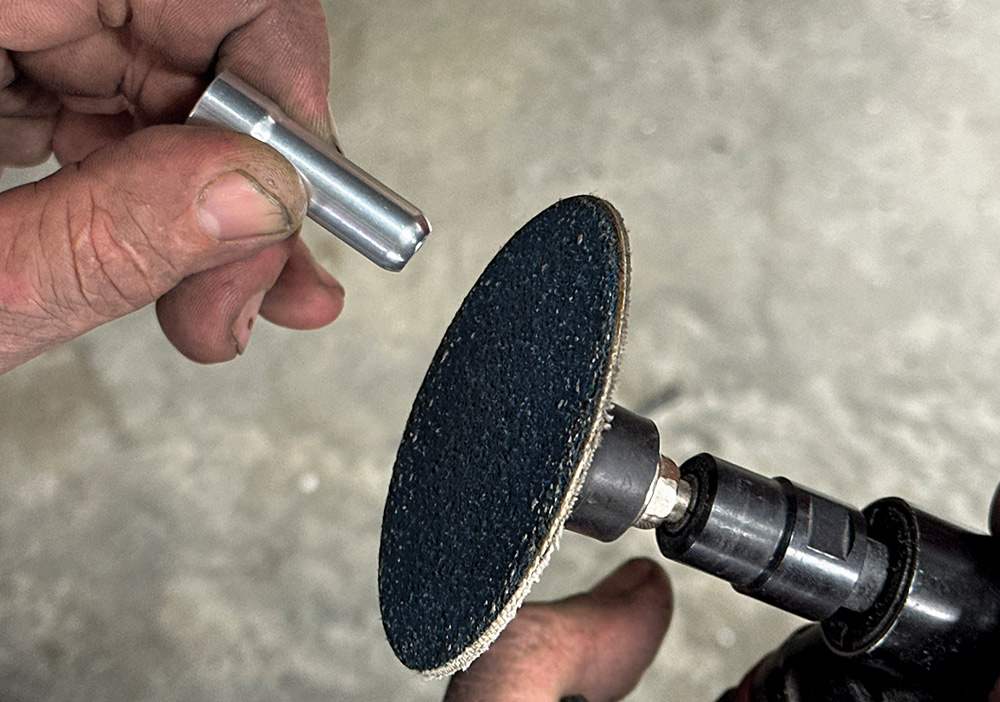
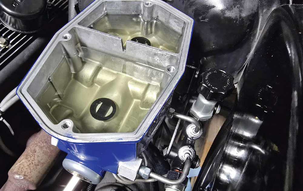
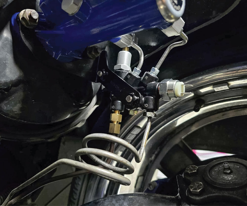
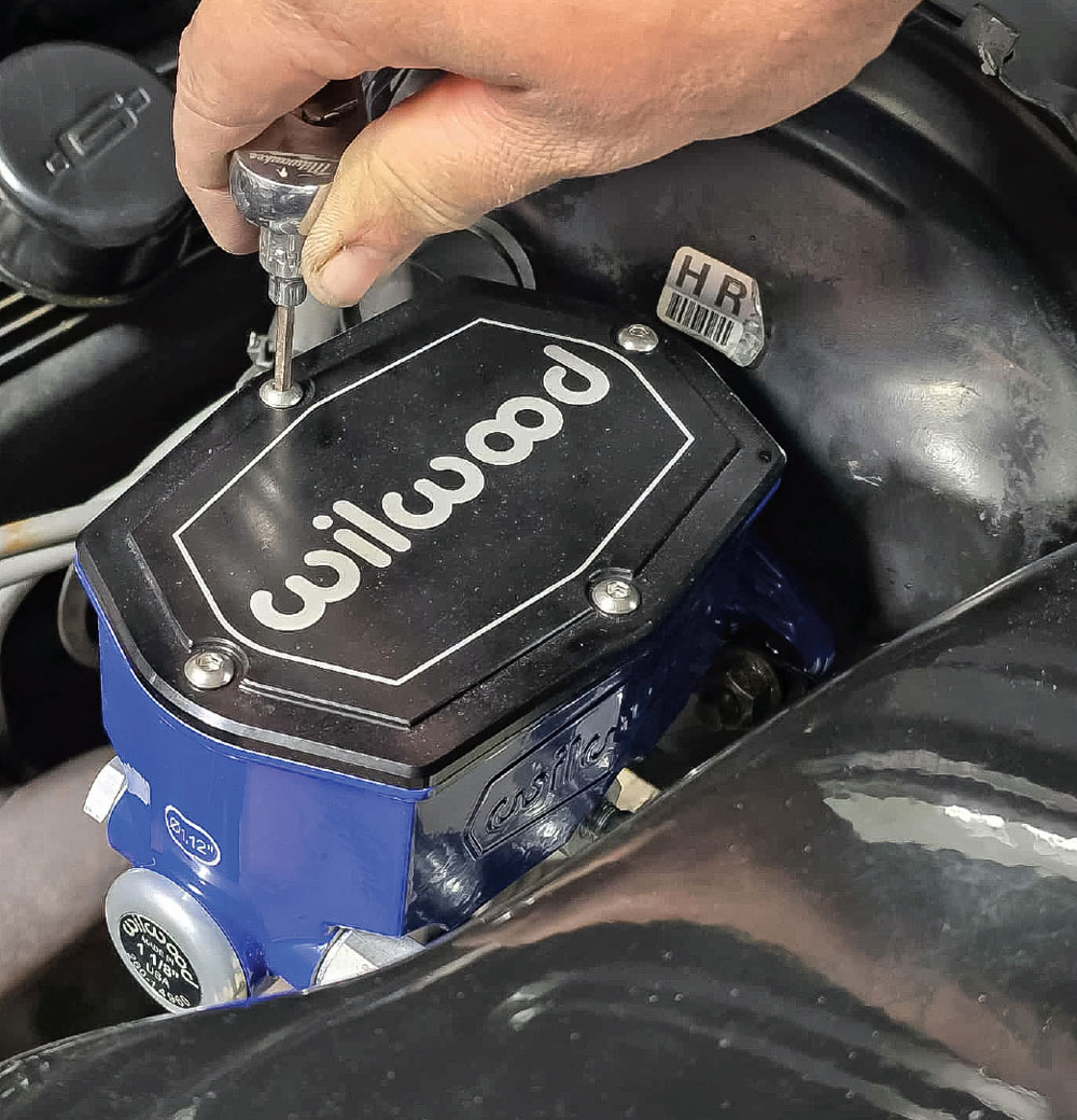
Master Cylinder