CTP Tech
InTheGarageMedia.com
quarter view of a grey GM C10 truck on a residential street
1. GM C10 trucks have never been more popular with great styling and can accept muscle car power upgrades. The Aldan American coilover kit used here fits ’66-87 trucks.
Trucks Don't Handle ... typography

And Other Myths Dispelled With a Coilover Kit From Aldan American

BY Cam BentyPhotography BY THE AUTHOR
T

rucks are utility vehicles. Ask any old-timer chassis engineer from one of the original Detroit Big Three car companies and they will undoubtedly announce that back in the day trucks had one singular purpose: haulin’ stuff! That certainly was the original plan when General Motors’ C10 chassis arrived on the scene starting in 1960. Back then, only farmers really needed trucks, the rest of us were completely happy with big sedans and assorted muscle cars. But the truck market is massive today, with both regular folks who need to “haul stuff” and enthusiasts. We insist that today’s new trucks haul everything from fresh cut wheat to a team of 10-year-old soccer players with ease and comfort.

Obviously classic trucks have had a huge resurgence for a number of reasons, including their low cost; simple, modifiable drivetrains; and cool designs, just to hit the high points. Interestingly, the utilitarian aspect of these classic vehicles has taken a back seat to the fun-to-drive aspects they now deliver (pun intended). But those classic trucks still need a lot of help in the handling department. Enter Aldan American with their advanced coilover conversion system.

Coilover vs. Spring
When GM, among other manufacturers, designed their double A-arm suspension systems, the intention was to deliver a lightweight, strong, reliable, and inexpensive way of supporting their vehicles. The standard suspension system utilized on older C10 pickups (especially our target for this article, ’63-87 models) featured a pair of differently sized A-arms that serve as a mounting point for the spring, brake, and steering components. Aldan offers three kits for C10s, including ’63-70 (PN 300140), ’71-72 (PN 300141), and ’73-87 trucks (PN 300142). On Kayla’s truck, the front spindles had been changed to the ’73-87 one-piece spindle that required different tie-rod ends and ball joints—good information to know when ordering your kit.

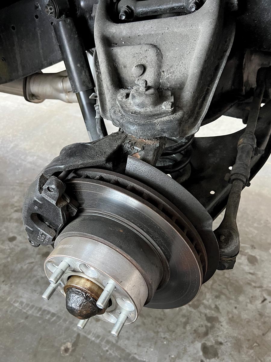
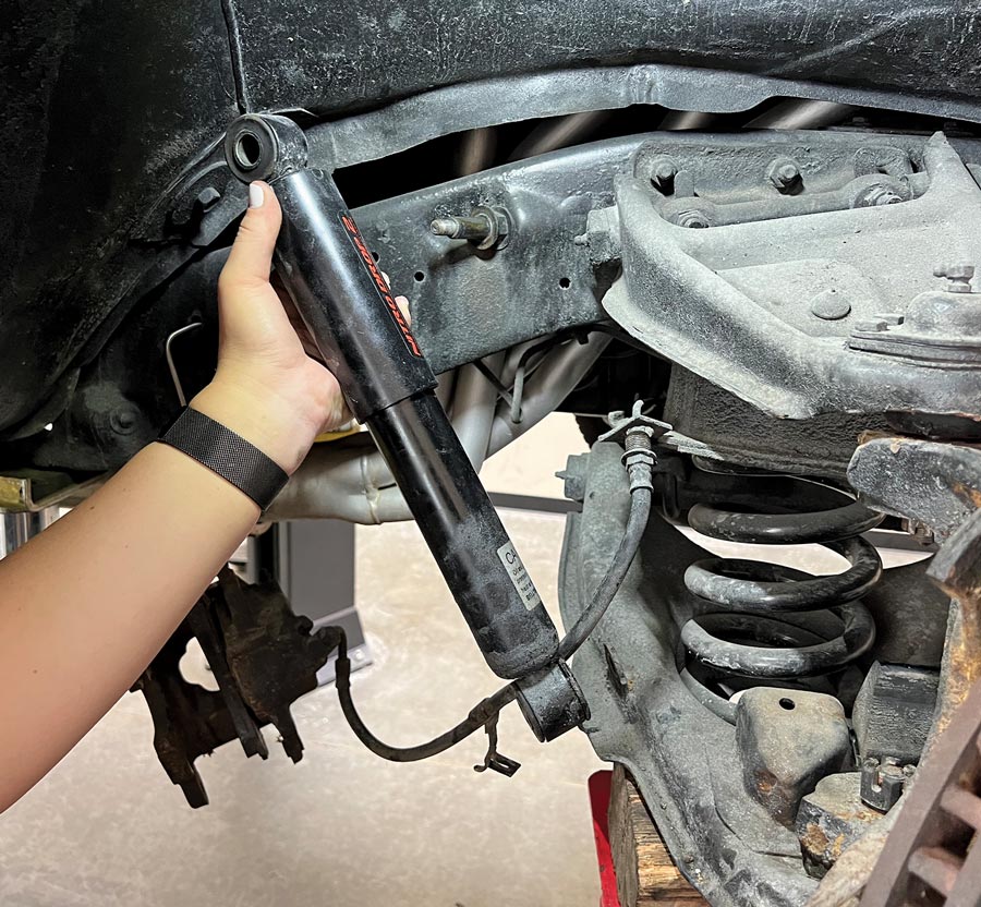
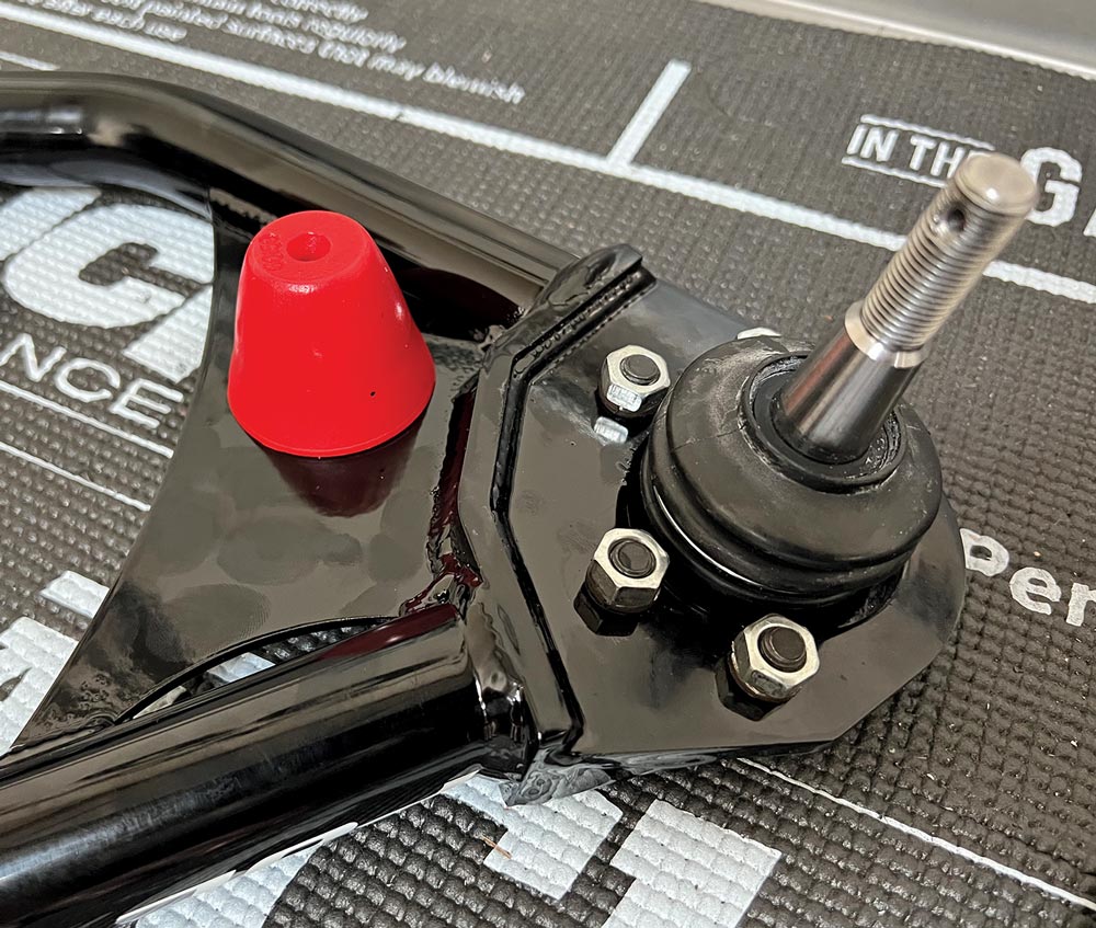
On ’63-87 GM C10 pickups, Aldan American does away with the independent tubular shock and coil spring and creates a coilover unit (coil spring and shock in one) that suspends the vehicle all on its own. The coilover from Aldan American can be tuned with differently rated coil springs (also offered by Aldan American) along with the ability to tune the shock valving by simply turning a knob(s) on the coilover to adjust either the compression (single-adjustable coilover) or compression and rebound (double-adjustable coilover).

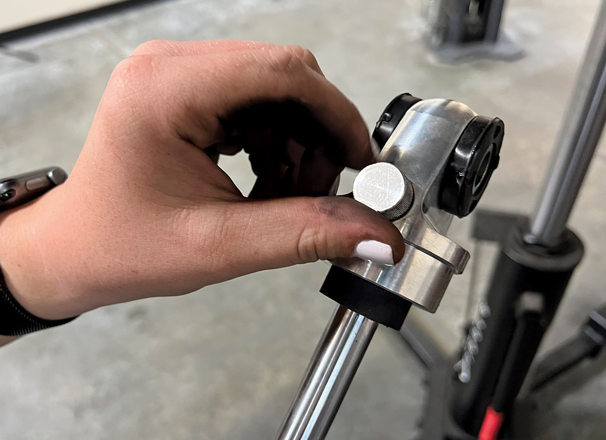
Finally, with the Aldan American coilover system you can lower the ride height of the vehicle by as much as 2 inches by turning a billet collar that rides on the threaded shock body (using a special wrench available through Aldan American) that serves as the bottom mount for the coil spring. This adjustment allows you to reduce the calculated roll center of the suspension for greatly improved handling. With the exception of changing the coil spring, these adjustments can be completed without removing the coilover from the vehicle—that’s some pretty incredible versatility that those original GM C10 suspension designers back in the day could never have envisioned.

The Installation
Kayla, the owner of the ’69 C10 pickup, performed all the operations shown here. Aldan American has developed a kit that incorporates Performance Online tubular A-arms and assorted hardware—a deserving upgrade for this very cool pickup. In total, the installation of the complete coilover kit took under 2 hours. For the rear suspension, we did not install a coilover system but rather Aldan American’s smooth body shocks that also feature either single or dual adjustability for compression and rebound and mount in the stock factory shock locations without modification.

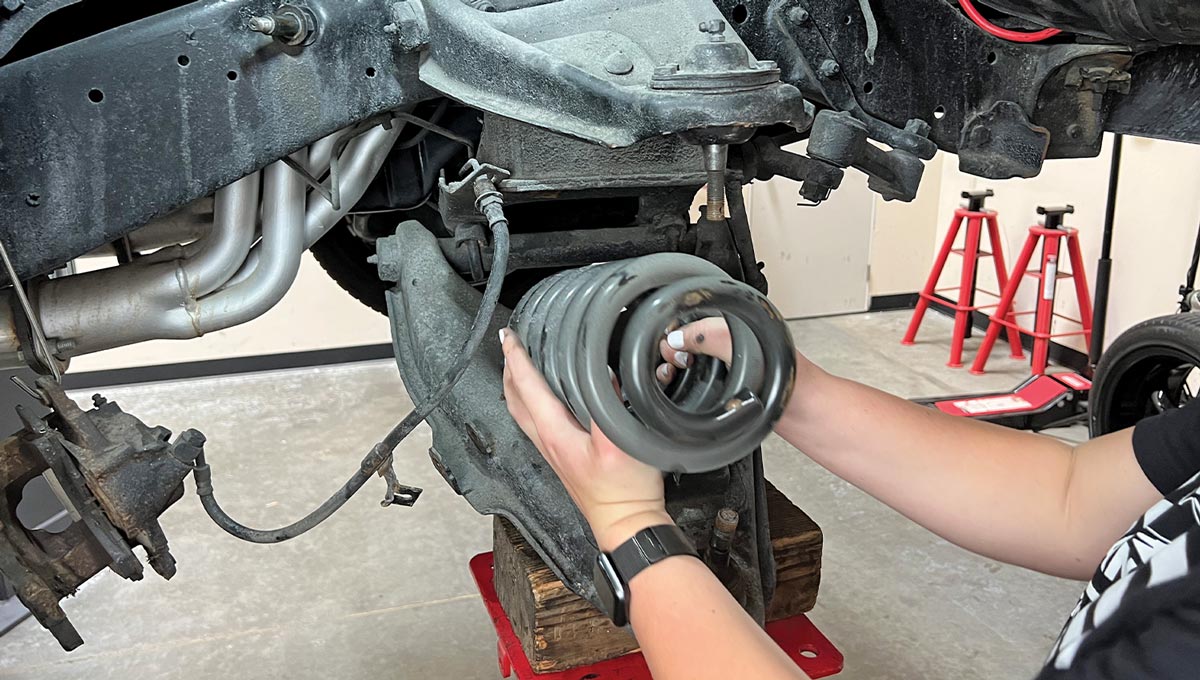
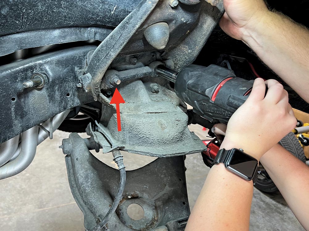
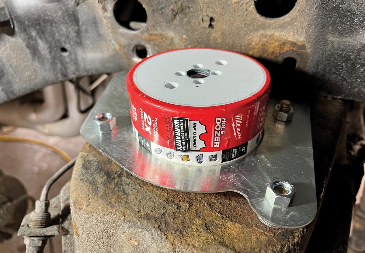
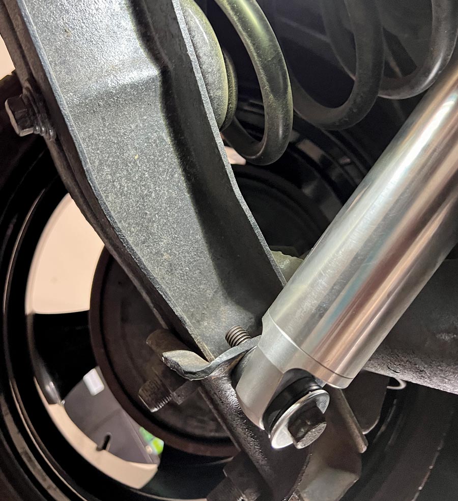
For this upgrade, Kayla’s white nail polished finger darkened significantly during the process. Having never worked on suspensions before, her abilities and the excellent design of the kits we used was on full display. The Aldan American front coilover upgrade can be performed with simple hand tools with one exception: the front suspension of our pickup had to be modified with a hole saw to create a hole in the front crossmember so the coilover can pass through.

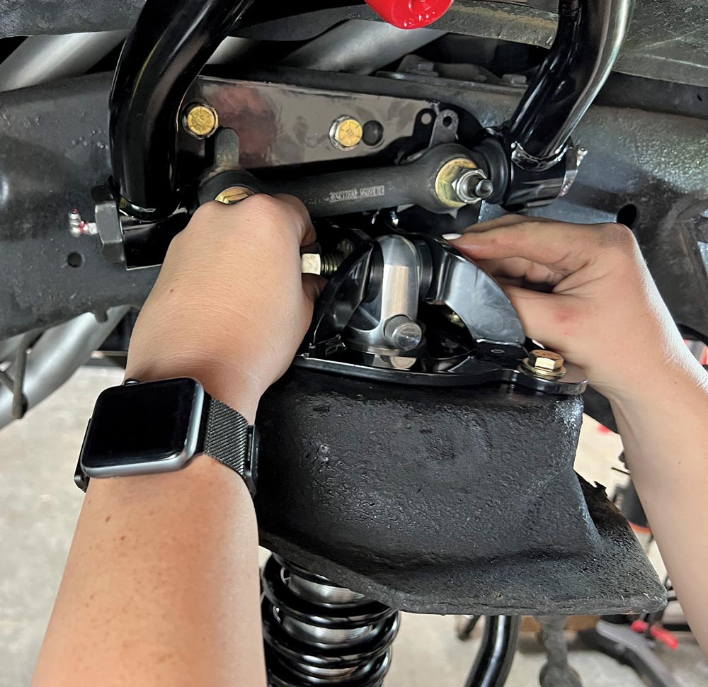
Aldan American provides clear instructions throughout. The coilover kit includes a template to help position the saw as you cut through the crossmember. We used a right-angle air drill to spin the hole saw after mounting the ingenious guideplate designed by Aldan American’s Gary Nelson. In the end, the coilover fits up through this plate with no interference and all the handling and ride benefits promised by Aldan American. The kit will mount in the original component locations if you are using standard-mount shocks.

So take a ride in our C10 as we help this truck handle the curves like it originally handled a bale of hay. The conversion to modern handling components is simply amazing and easy to complete.

Aldan American coilovers, smooth body rear shocks and a full suspension “makeover” kit from Performance Online organized on a work table
2. For this installation we used Aldan American coilovers and smooth body rear shocks along with a full suspension “makeover” kit from Performance Online that features tubular A-arms, bracketing, and all-new hardware.
a measuring tape hangs by a rear tire as it is used to determine the body ride height clearance
3. The Aldan American coilovers allow you to lower the vehicle as much as 2 inches if the tire/wheel clearance is sufficient. We measured the body ride height before and after the conversion to help ensure everything is even side-to-side. If further lowering is desired, drop spindles can be used to achieve a 4.5- to 5-inch lower ride height.
close view of an axle shaft end
4. Our ’69 C10 sported all of the original-style components with upper and lower A-arms and separate shock arrangement.
a hand torques a nut while disassembling the suspension
5. When disassembling the suspension, a factory maintenance manual is recommended to safely complete the work. We started by safely raising the chassis and then removing key parts, like the tie-rod ends, brakes, and sway bar, if your truck is so equipped.
two combination wrenches are used to loosen nuts in a tight space
6. This very cool tool presses out the upper and lower ball joints at the same time without damaging them. After removing the cotter pins top and bottom and loosening the nuts a few turns, by expanding this tool you can pop out the ball joints. It is important to remember that this ’69 C10 had been upgraded to ’73-87 spindles requiring different ball joints and tie-rod ends.
a hand holds a freshly removed shock absorber
7. The shock absorber on C10 trucks is positioned behind A-arms. Remove the bolts that hold it to the chassis and A-arm mount to release it. The upper shock mount on the chassis will also be removed as it will no longer be used with our new Aldan American coilover kit.
two hands carefully remove a coil spring from the lifted truck
8. After the ball joints are disengaged, support the lower A-arm and slowly remove the coil spring. We recommend that you use a spring compressor to contain the coil spring as there is a lot of energy that can be released all at once if you are not careful.
a red arrow points to one of two bolts to be removed from the chassis to release the upper A-arm
9. Remove the two bolts shown here (arrow and impact gun) and remove the upper A-arm from the chassis. You will have to hold the head of the bolt from that back side of the frame.
close back view of a U-bolt still holding a lower A-arm to the chassis
10. The lower A-arms are held to the chassis with a pair of U-bolts. These bolts on our truck had not been removed in a while—probably not since the truck left the factory.
view of a plate that attaches to the crossmember where the A-arms used to be
11. With the A-arms out of the way you can reach this plate that attaches to the crossmember. We chiseled off the attaching rivet heads to release it.
a plate with a 4-inch hole trimmed in the center is place on the crossmember plate to be trimmed
12. To allow clearance for the coilover to pass through the crossmember, we had to cut a 4-inch hole. Aldan American includes a template that helps guide the saw when cutting. The silver plate (background) rides on these stacked washers to help keep the saw from slipping off as it cuts. Everything shown here is included in the kit.
a 4-inch hole saw dia is placed on the crossmember trim plate
13. The 4-inch hole saw (not included with the kit) is designed to cut the metal crossmember. Note how it fits into the guide.
close view of the 4-inch saw dia attached to a right-angle drill
14. This right-angle drill makes it easy to cut through the crossmember. Using a little lubricant on the saw blade teeth helps with the cut.
a small angle grinder is used to clear the metal and debris as well as smoothen the new hole
15. After cutting the hole, we smoothed the opening, removing all metal debris. Remember, this is where the coilover will pass through and it needs to be free of anything sharp.
view of the coilover mounting plate in position
16. The new coilover mounting plate looks like this when in position. Note that all-new hardware, part of the Aldan American kit, is used. We torque all the bolts to 55 lb-ft.
close view of a lower A-arm with a ball joints already installed
17. With the lower A-arms we had to install the ball joints before installation. We torqued all ball joint attaching hardware to 25 lb-ft. The lower A-arms come with the ball joints already installed.
a red arrow points to a locating dowel on the chassis covered with debris
18. This locating dowel must be free of debris as it serves a critical job of locating the lower A-arm mount
close view of a circular recess in the lower A-arm mounting shaft
19. The dowel pin noted in the previous image fits into this recess in the lower A-arm mounting shaft. This keeps the lower shaft from rotating in the chassis.
a U-bolt is reused to attach the lower A-arm mounting shaft to the locating dowel on the chassis
20. We reused the U-bolts and nuts from the original A-arm system for this step. If your parts are in any way worn or rusted, do not reuse them. Torque the nuts to 45 lb-ft.
close view of fingers grasping the single adjustment knob at the top of an Aldan American coilover
21. These Aldan American coilovers feature single adjustment—a rebound setting for the top knob (in a double-adjustment setting there would be a lower knob for compression adjustment). Aldan American advises starting at a midpoint in the rebound range by turning the knob counterclockwise until it stops and then three clicks clockwise. As you drive the vehicle you can adjust the setting to your liking.
a single bolt is used as the upper mount for the coilover
22. A single bolt, supplied in the kit, serves as the upper mount for the coilover. Note that the adjustment knob is facing outward so it can be accessed once in the vehicle. Torque this 5/8-inch bolt to 75 lb-ft. The bottom mount goes together in similar fashion.
view of the front suspension of the GM C10 truck with its new coilover and A-arms
23. When complete, the front suspension will look like this. Make sure to recheck the torque specs on all bolts and never reuse rusted or damaged parts.
view of the original rear suspension configuration, using a single shock
24. The original rear suspension configuration includes of a single shock. It attaches to the chassis in two points, as shown here.
close view of fingers adjusting the rear rebound setting on the Aldan American smooth body shock absorbers
25. As we did with the front coilover, we set the rear rebound setting on the Aldan American smooth body shock absorbers by turning the knob full counterclockwise then clockwise three clicks. Again, the knob should be facing outward to access once the shock is installed.
close view of the end of a newly installed shock, secured using an original bolt
26. We installed the shocks using original hardware and torqued the bolts to 70 lb-ft, top and bottom.
the Aldan American kit provided wrench is used to make an adjustment to the lower spring mount
27. This wrench is part of the Aldan American kit and allows for adjustment of the lower spring mount. By adjusting this mount, you can lower your truck’s ride height by up to 2 inches, depending on tire-to-fender clearance.
the owner, Kayla stands beside her grey ’69 C10 truck parked in a lot

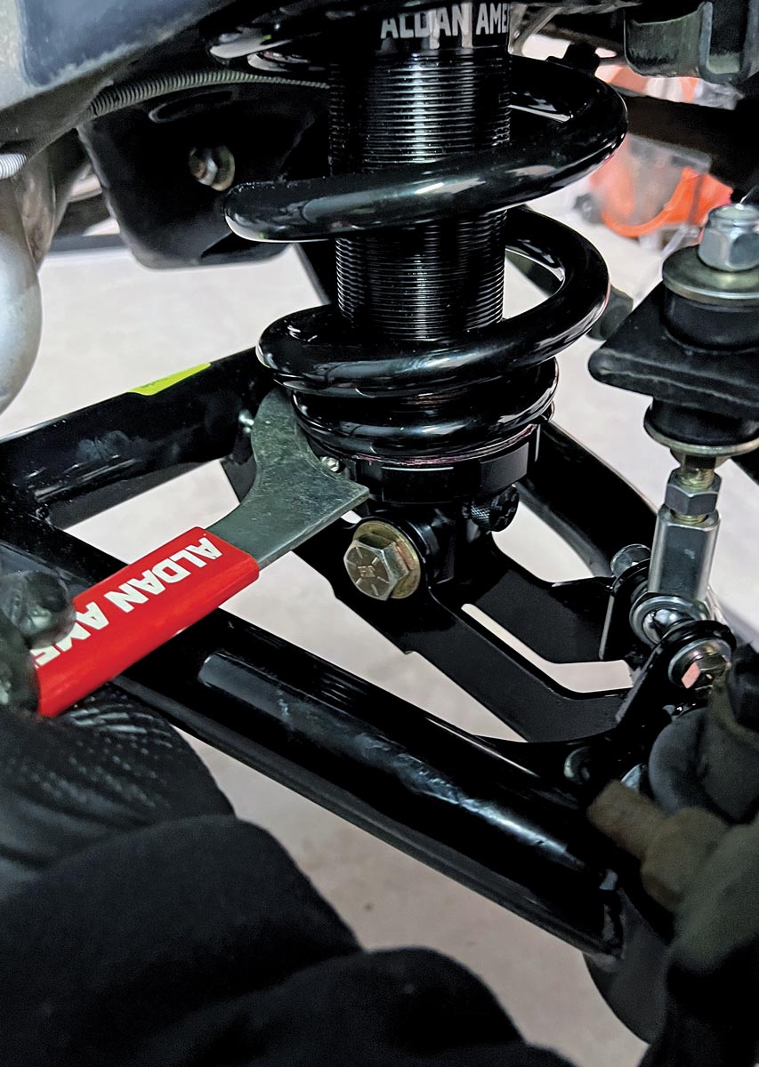
28. Kayla’s ’69 C10 is a sharp runner with lots of new chassis parts. These upgrades allow for amazing tunability not only for ride quality but also for stance as we can now lower the chassis as much as 2 inches in the front.

SOURCE