Tech
InTheGarageMedia.com
Top down view of twin-turbo LS in '68 Chevy truck
"Modern Technology: 3D Printed Hammerforms"
BY Ron Covell
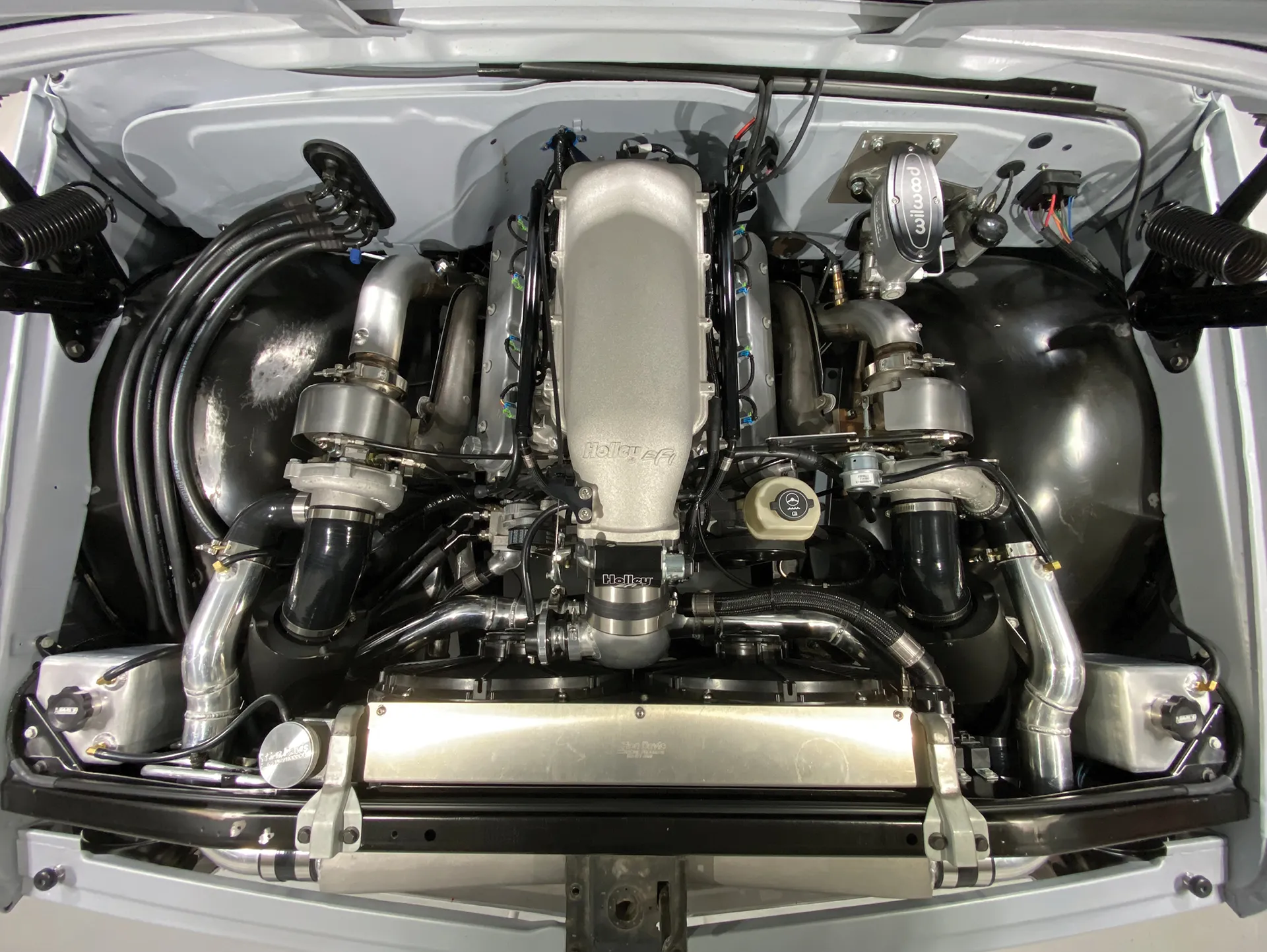
PHOTOGRAPHY BY Adam Cecil
H

ammerforming is one of the oldest metalworking processes around. It involves making a form from some durable material in the shape of the desired part, clamping a sheet of metal to it, and hammering the metal until it takes on the shape of the form.

Often these forms were made from wood, since it is fairly easy to work and the harder grades of wood provide enough durability to be used indefinitely. A properly constructed hammerform allows even a beginning metalworker to make a part that looks die stamped.

Technology always evolves, and a few computer-savvy metalworkers have realized that the new, affordable desktop 3-D printers can be used to make excellent hammerforms, with no sawdust involved!

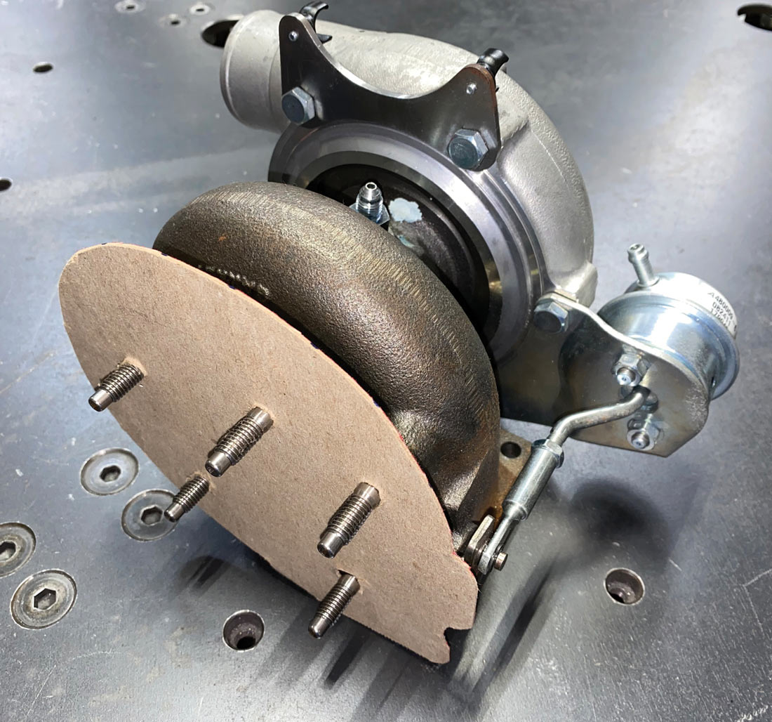
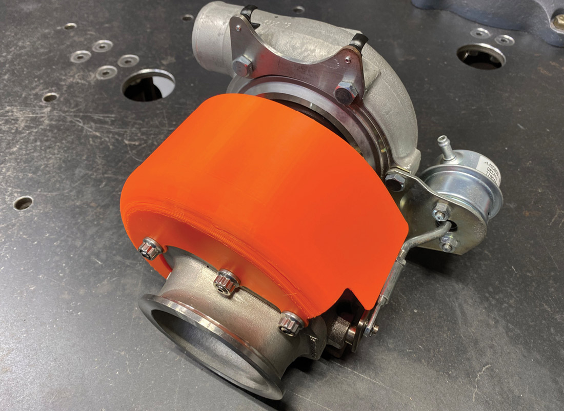
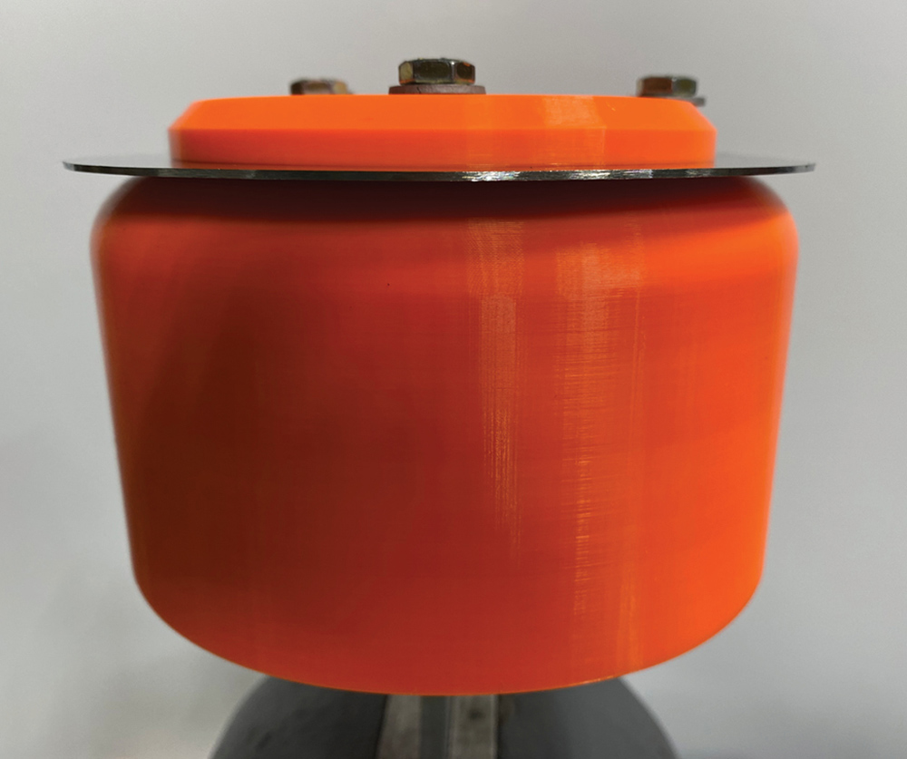
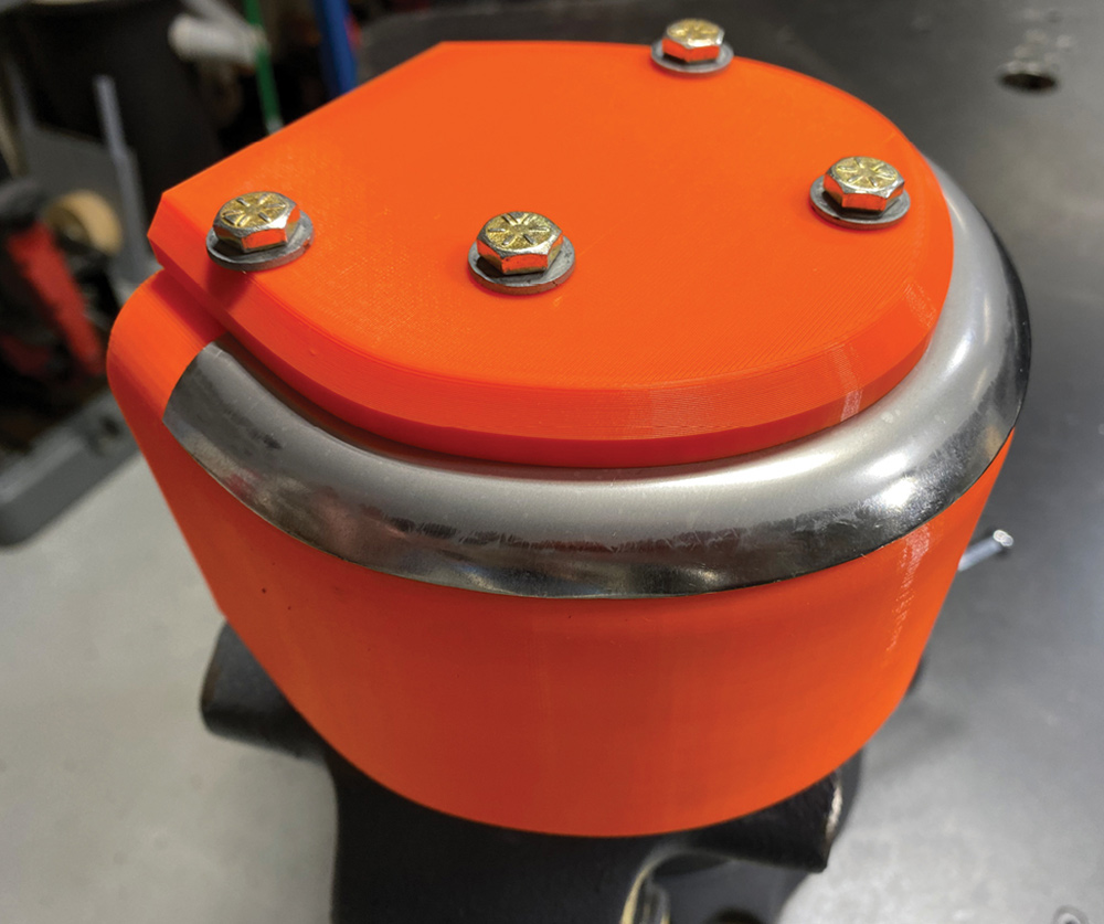
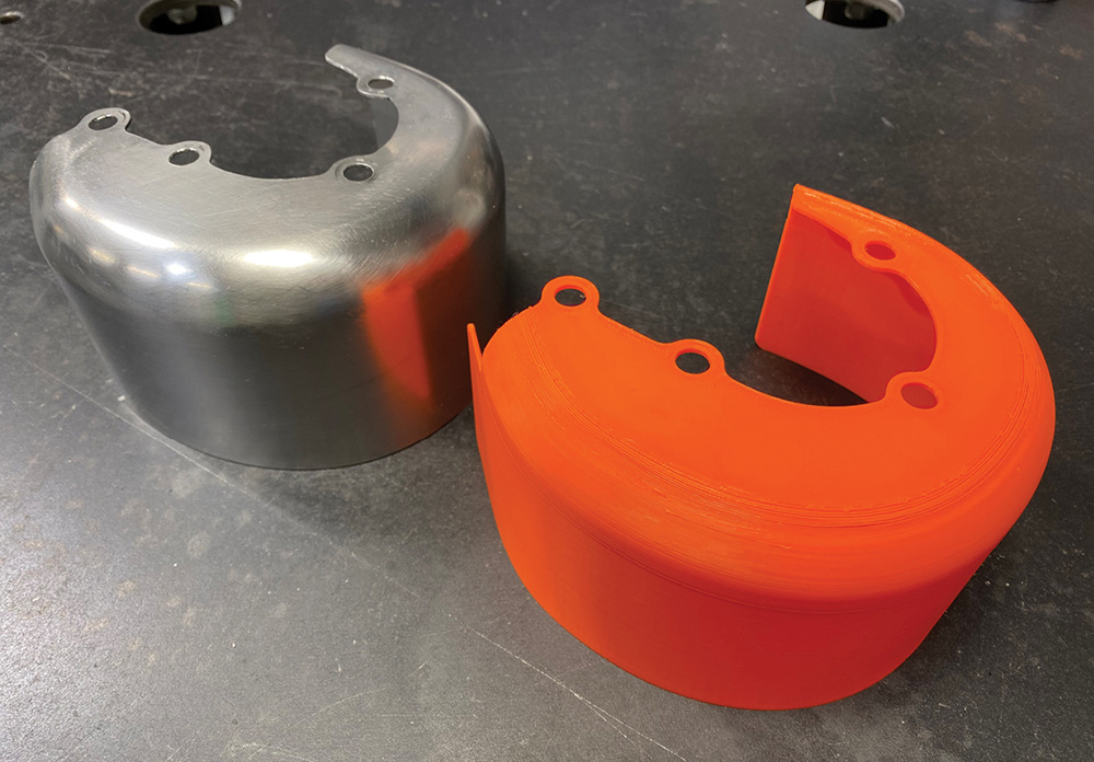
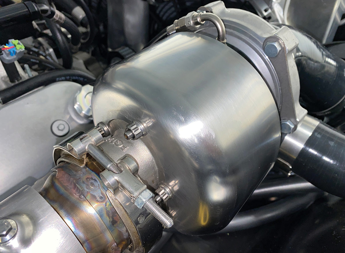
In this article, we will follow the work being done by Adam Cecil, a classic truck enthusiast who has had great results using this process. We’ll take a detailed look at the stainless turbocharger heat shields he made and a pair of tanks for the coolant overflow and the windshield washer fluid. All of these are for his ’68 Chevrolet truck with a twin-turbo LS engine.

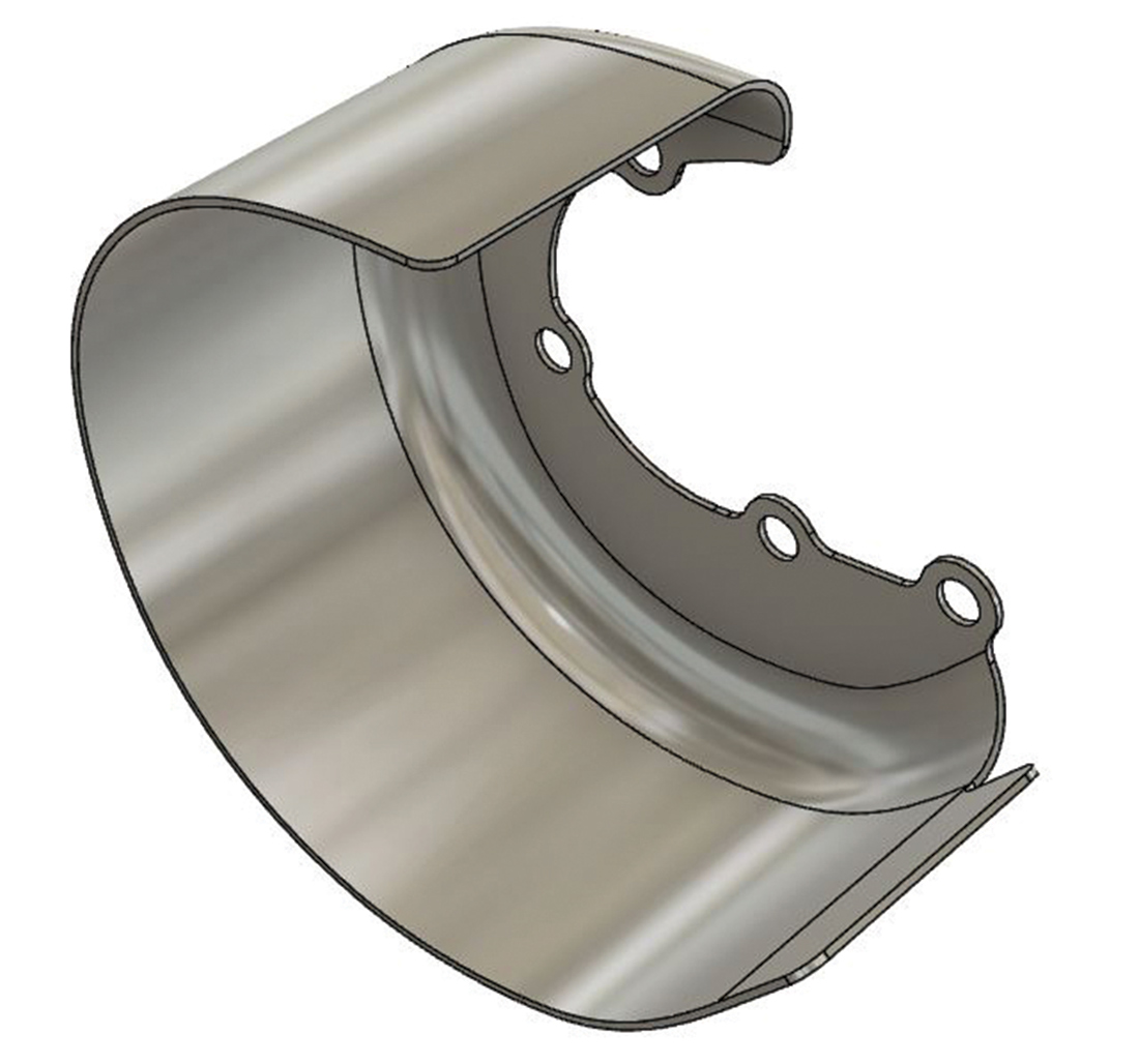
The first step is to create a computer model of the part to be made. These days there are many choices for CAD (computer-aided design) software, but Cecil uses Fusion 360 from Autodesk, which is available as a free download.

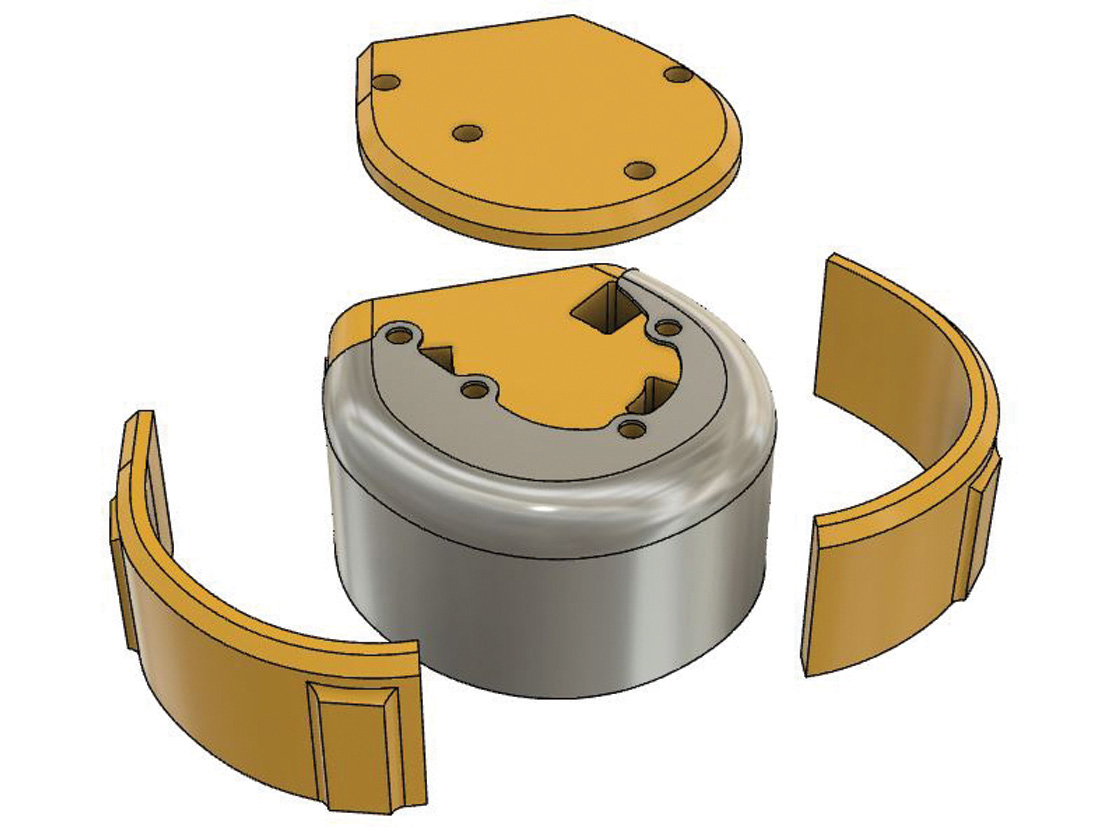
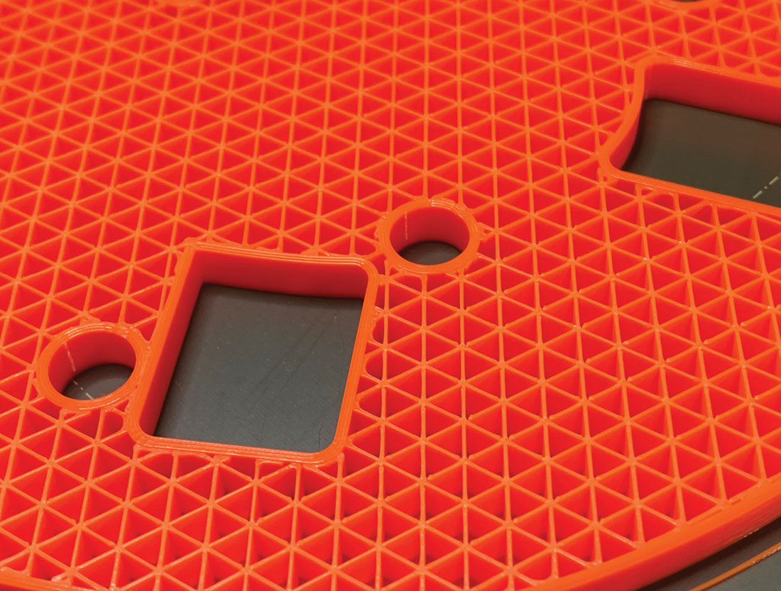
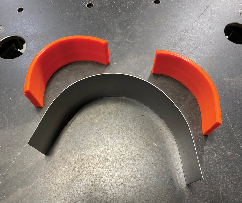
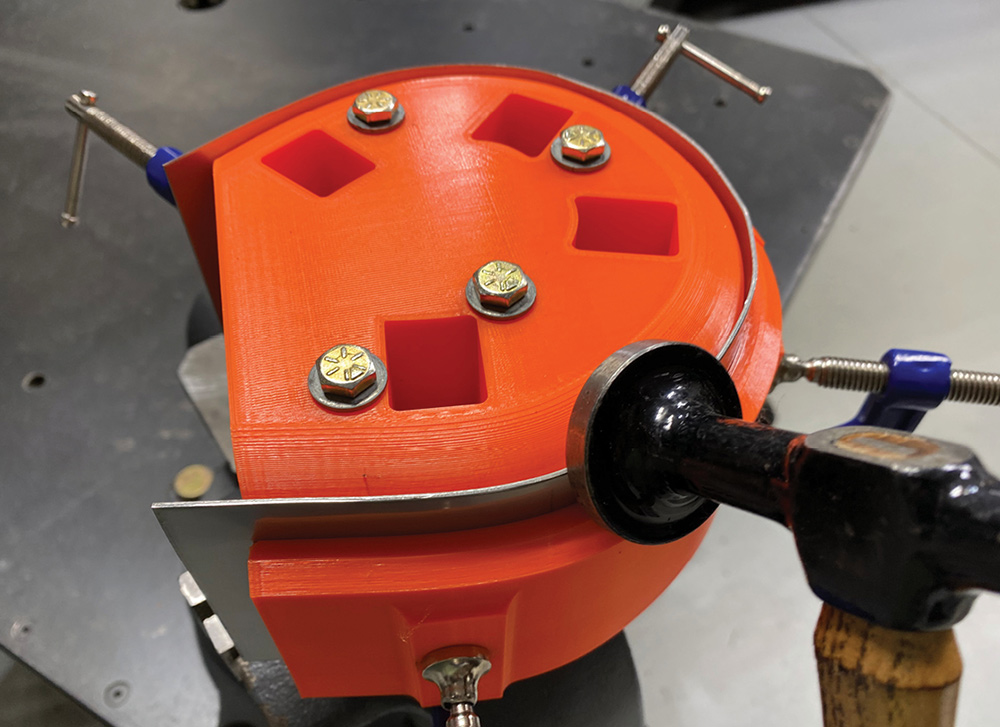
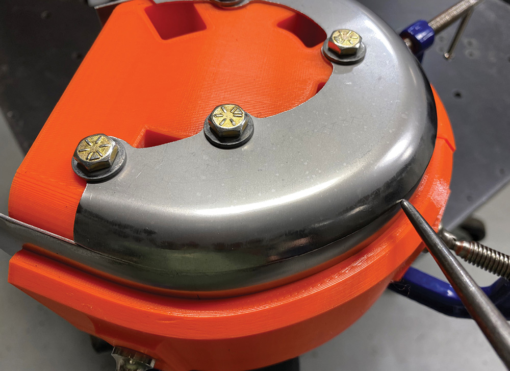
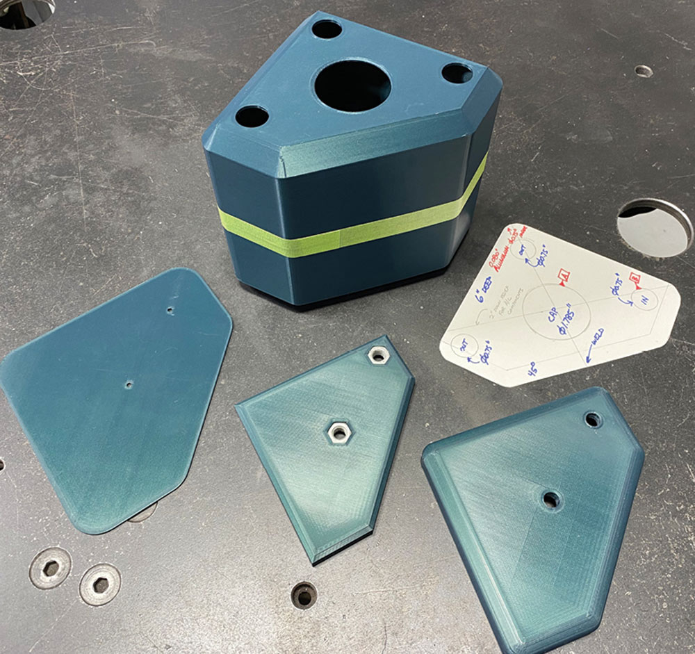
After the CAD model is created, the next step is to design the hammerform and clamping blocks, which will be a snug fit inside and outside the model. Alignment pins are generally used to keep the parts properly aligned and, when possible, these are made to coincide with features on the finished part so no extra holes will have to be filled. For the turbo cover, Cecil used the studs for the turbine outlet/wastegate cover for the alignment pins; for the fluid tanks, he used the centers for the cap and the plumbing fitting.

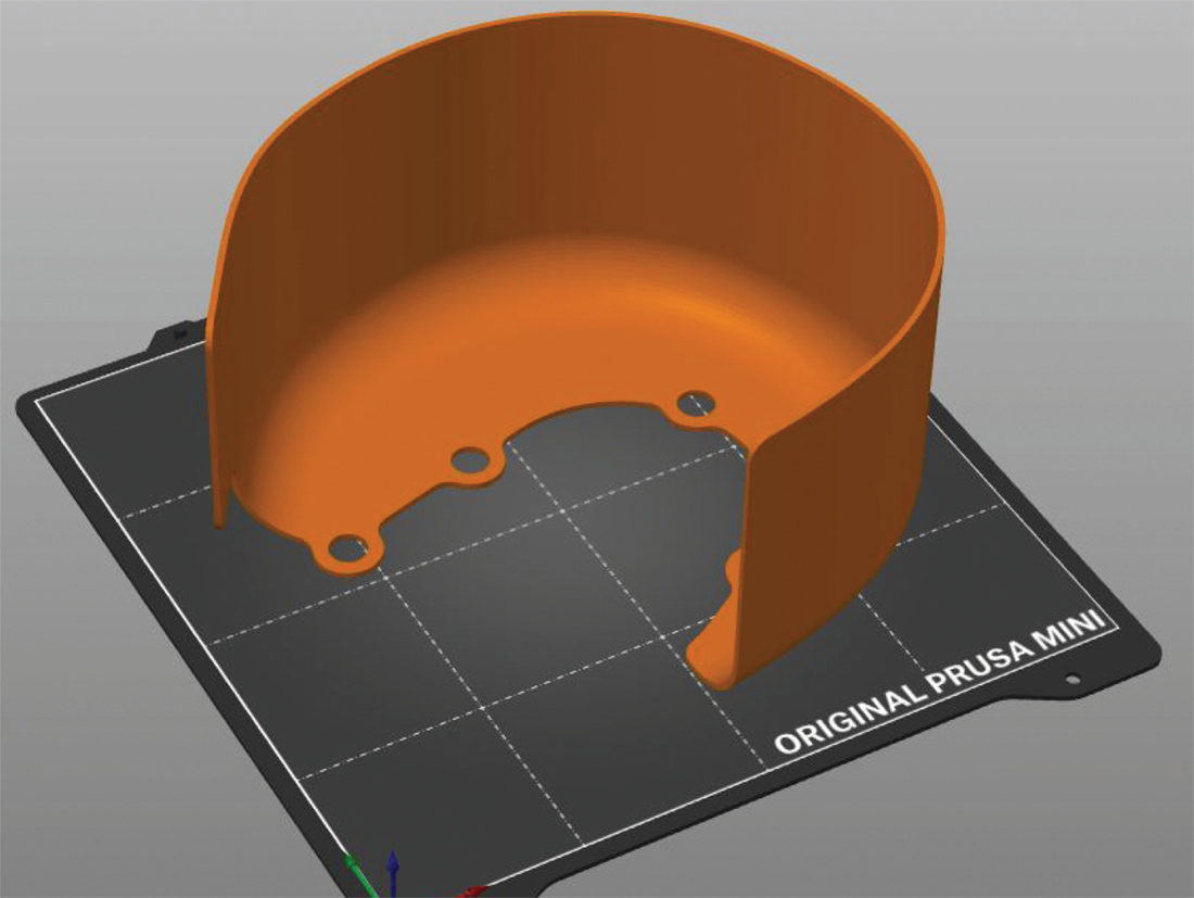
Once the parts have been designed in CAD, another software package is required to generate the G-code that the printer runs on. Cecil used another free software package for this called PrusaSlicer.

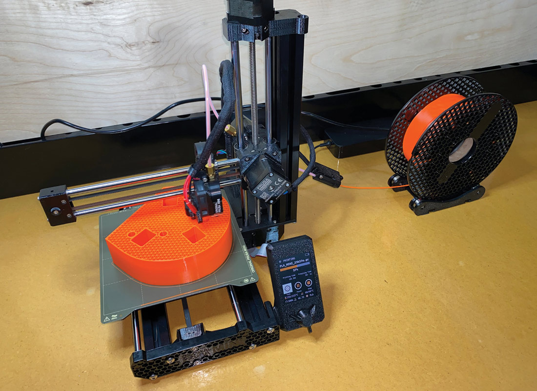
There are many printers on the market, at widely ranging price points. Cecil chose a Prusa Mini+ printer. Its build volume is a 7-inch cube. He reports they provide excellent customer support. This printer is just over $400 in kit form, but several other companies make simplified versions that start around $200. You get more features at the higher price points but the entry-level machines are VERY affordable these days.

There are many different filaments used for 3-D printing. Cecil chose PLA, one of the most common, and a 2.2-pound spool costing $30 was sufficient to print the hammerform and clamping blocks for the turbo heat shield.

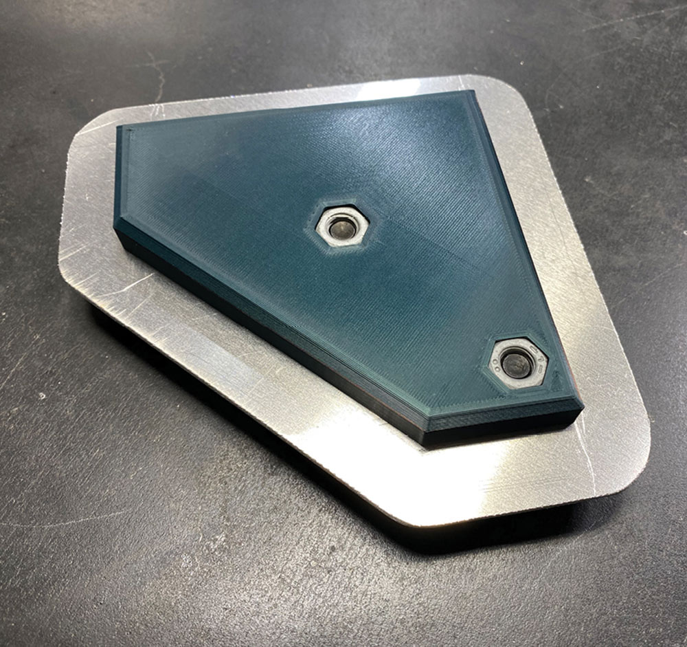
It took about 24 hours to print the parts needed for the heat shield, but the printer can run unattended, day and night.

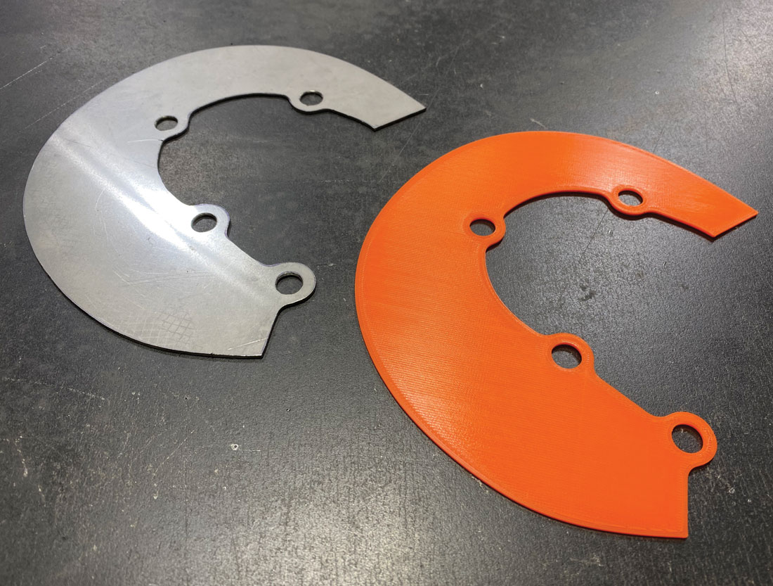
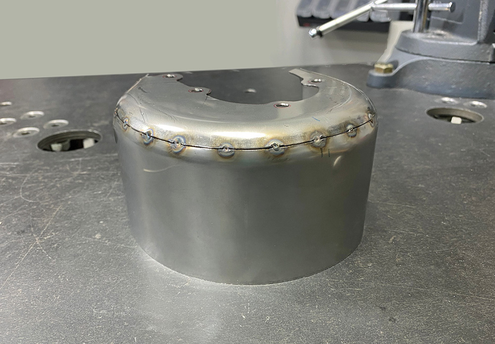
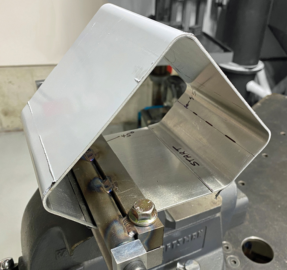
Once the forms were printed, it’s a simple job to cut the metal blanks, clamp them in place, and hammer the edges. Then the parts can be fitted together and welded. Once the welds are smoothed you are left with a clean, accurate construction that rivals the look of a die-stamped part!

Look through the accompanying photos to see the details of this process. It could open up a whole new world of possibilities for many classic truck builders!

Turbocharger with cardboard mockup on endcap
1. A great way to start any project is with a chipboard pattern. This shows the rough layout for the endcap of the turbo heat shield, which will provide about a 1/4-inch air gap all around.
Auto CAD rendering of turbo's shield
2. This is a computer rendering of the completed shield, made with Fusion 360 CAD software, which can be downloaded free from Autodesk.com.
Auto CAD rendering of shield hammerform and clamping blocks
3. Here’s a rendering of the hammerform and clamping blocks. It helps visualize the parts before printing to see if any revisions are required.
Rendering of model in Prusa Slicer software
4. This is a rendering of what the printed model will look like. It’s always best to print and test a model before making the part from metal.
Prusa Orange 3D printed model test fitted to turbo
5. The printed model is test-fitted on the turbocharger. Cecil went through a few revisions until he was happy with the fit. This prototype took four hours to print.
Hammerform being printed on Prusa Mini
6. The hammerform is being printed here one thin layer at a time. You can see the coil of filament that feeds the heated print head.
Closeup of partially printed hammerform showing triangular patterned infill
7. Here’s a close-up of the partially printed hammerform. Note that the borders of all features are printed solid, but the infill areas are left 40 percent open. This speeds the printing considerably and saves material.
3D printed mockup of first hammerform piece next to steel sheet cut to match
8. A mock-up was made for the first part to be hammerformed and checked on the buck. After verifying the dimensions, a piece of 18-gauge stainless sheet was cut to match.
Printed clamping block, stainless blank and printed hammerform in vise
9. From top to bottom: the clamping block, the stainless blank, and the hammerform itself. This assembly is held in a vise to hold it at a convenient height while hammering.
Steel sheet after initial hammerforming
10. Here’s the part after the initial hammering. As you can see, the printed hammerform provides all the strength required for this application, even with stainless steel.
Steel sheet and printing clamping blocks
11. The stainless band for the perimeter of the heat shield is bent to the approximate shape and is shown along with the printed clamping blocks.
Using body hammer on 2nd clamped steel sheet
12. With all the parts assembled and clamped, a standard body hammer is used to form the stainless sheet against the printed hammerform.
Formed endcap
13. The formed endcap was made slightly oversize. Here it is laid over the perimeter piece and the overlapped area is scribed for trimming. This will make a tight butt joint—ideal for welding.
Endcap and shield tack welded together
14. The parts are tack-welded together off the hammerform.
Finished part next to printed model
15. Compare the finished part with the printed mockup; they are virtually identical in size and shape.
Heat shield attached to turbo
16. Here’s how the heat shield looks mounted to the turbo. It keeps the heat away from sensitive components and presents a very attractive appearance underhood.
3D printed parts for washer fluid resevoir
17. The hammerforming process can be used for all sorts of parts. This is the printed form for a windshield washer fluid reservoir.
Endcap hammerform and aluminum blank bolted together
18. This is the hammerform and aluminum blank for the endcap of the tank. Note the recesses provided for steel nuts allowing the plastic parts to be bolted tightly against the metal.
Formed tank perimeter in vise
19. The perimeter of the tank was formed in a clever homemade radius brake, which mounts in a vise.
Finished tank next to printed mock-up
20. Here’s the finished tank alongside the printed mock-up. A similar tank was made for the other side of the truck to capture coolant overflow.