CTP Tech
InTheGarageMedia.com
two men positioning a new bolt-in Mustang II independent front suspension crossmember
1. Saying goodbye to Ford’s twin I-beams, Danny Nix, engineer at Classic Performance Products (CPP) and Gary Ash position the new bolt-in Mustang II independent front suspension crossmember for ’65-79 F-100s.
Swapping
I-Beams for IFS
Classic Performance Products’ Bolt-In Suspension System for ’65-79 Ford Trucks
BY Ron CeridonoIMAGES BY CTP Staff
I

n 1948 Ford introduced their first generation of 1/2-ton pickups, the F-1. They were revolutionary in so far as they were no longer based on passenger car frames and suspension components like all Ford’s light-duty trucks that had come before. The second generation of the F-series trucks were produced from 1953-56. This series of trucks had been redesigned once again, the 1/2-ton versions were now identified as F-100s and 3/4-ton trucks were now F-250s. The third generation of Ford pickups from 1957-60 were treated to another face-lift. While several updates had been made to the chassis at this point, the same basic design could be traced back to the ’48 F-1; at both ends were solid axles with parallel semielliptic leaf springs—simple but effective.

The fourth generation of the F-series trucks were produced from 1961-66. Up to this point annual sheetmetal and trim changes were made for a fresh look, but the chassis remained much the same as those that had come before, that is until a big change was made midway in 1965. A completely new chassis was introduced that included Ford’s infamous twin I-beam front suspension. This layout used two I-beam axles, each anchored to the frame on one side of the frame with the wheel on the opposite side of the truck. The idea was the long individual axles would allow each wheel to act independently while maintaining the strength of a conventional single I-beam.

For the fifth generation of the F-series, from 1967-72, and the sixth generation, from 1973-79, there were styling changes and improvements in interior comfort but the twin I-beam front suspension remained in play. And to a great degree that suspension system is why ’65-79 Ford pickups have often been overlooked by early truck aficionados. Despite the fact that these pickups are good looking, the twin I-beam configuration was not one of Ford’s better ideas. These front ends had very little caster, so a common complaint was poor straight line stability and wandering on rough roads as a result of the camber change as the wheels moved up and down at the end of the individual axles. These front ends were also known to be hard on tires and could lay waste to a pair of shock absorbers in short order.

While ’65-79 Ford pickups are readily available for reasonable prices (particularly when compared to C10s) the problem for the CTP faithful has always been that twin I-beam Fords have handling limitations, the steering boxes are notoriously leak prone, and perhaps worst of all from our perspective is they are difficult to lower correctly. There’s no arguing that stance is a critical part of building a cool truck of any make, and lowering is a key component of that, which is a big problem when building a Ford of that era. But for every problem there is a solution, and the best way to get a Ford closer to the ground while simultaneously improving its ride and handling characteristics is to install a Classic Performance Products (CPP) bolt-in Mustang II Front Suspension Kit for ’65-79 F-100/F-150s.

Although the Mustang II was forgettable, the front suspension will always be regarded as the best feature of those cars. The Mustang II had a surprisingly stout front end with bigger wheel bearings than the Chevy Nova clip swaps that were once popular. The ball joint and tie-rod end studs are the same size used on fullsize Fords and the front mount rack-and-pinion steering that makes room for virtually any engine. Given all that and the fact that it is easily adaptable to a variety of applications, it’s hard to find fault with a Mustang II suspension system.

CPP has gone to great lengths to make installing their IFS kit easy. Once the stock Ford axles, spring brackets, and crossmember are removed, CPP’s Mustang II crossmember and upper control arm brackets bolt in place, with no welding required. By using factory holes locating the new crossmember and upper control arm brackets is foolproof—and only six additional holes have to be drilled to complete the installation.

Along with the beautifully crafted main crossmember and control arm brackets the CPP kit includes a new manual or power rack-and-pinion steering gear, stock or dropped spindles, new coil springs and shocks, 11.75-inch disc brake package, black powdercoated tubular control arms, 3/4-inch sway bar with billet mounts, and all the required hardware. Also available with this kit are CPP’s unique FitRite adjustable engine mounts to suit a variety of Ford engines as well as Chevy LS and LT V-8s. For those who want to run larger wheels, bigger brakes, and suspension adjustment capabilities, CPP offers a number of upgrades to the basic IFS kit that include Corvette-style spindles and hubs, 13-inch brake kit, and coilover springs and shocks. Additionally, this spindle and brake combination comes with spacers that allow the tread width to be reduced by 1/4 or 1/2 inch per side.

Ford pickups with twin I-beam suspension are often overlooked by classic truck enthusiasts because front suspension modifications have been seen as difficult to accomplish satisfactorily, but that has changed. CPP’s bolt-in Mustang II front suspension kit is the quick-and-easy way to swap those twin I-beams for IFS and gain the benefits of a smoother ride, better handling with the road feel of rack-and-pinion steering, along with the cool look a lowered ride height provides. There’s even more to come—CPP has more upgrades for fans of Ford’s iconic F-series trucks that we will reveal soon.
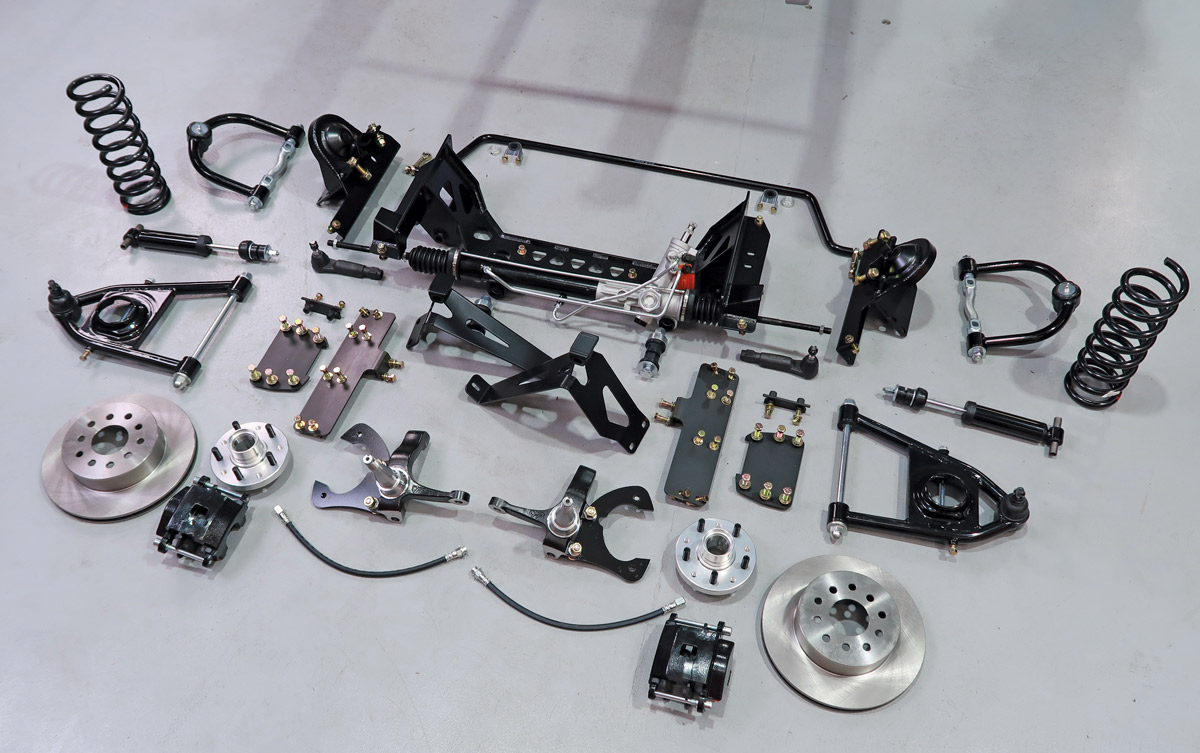
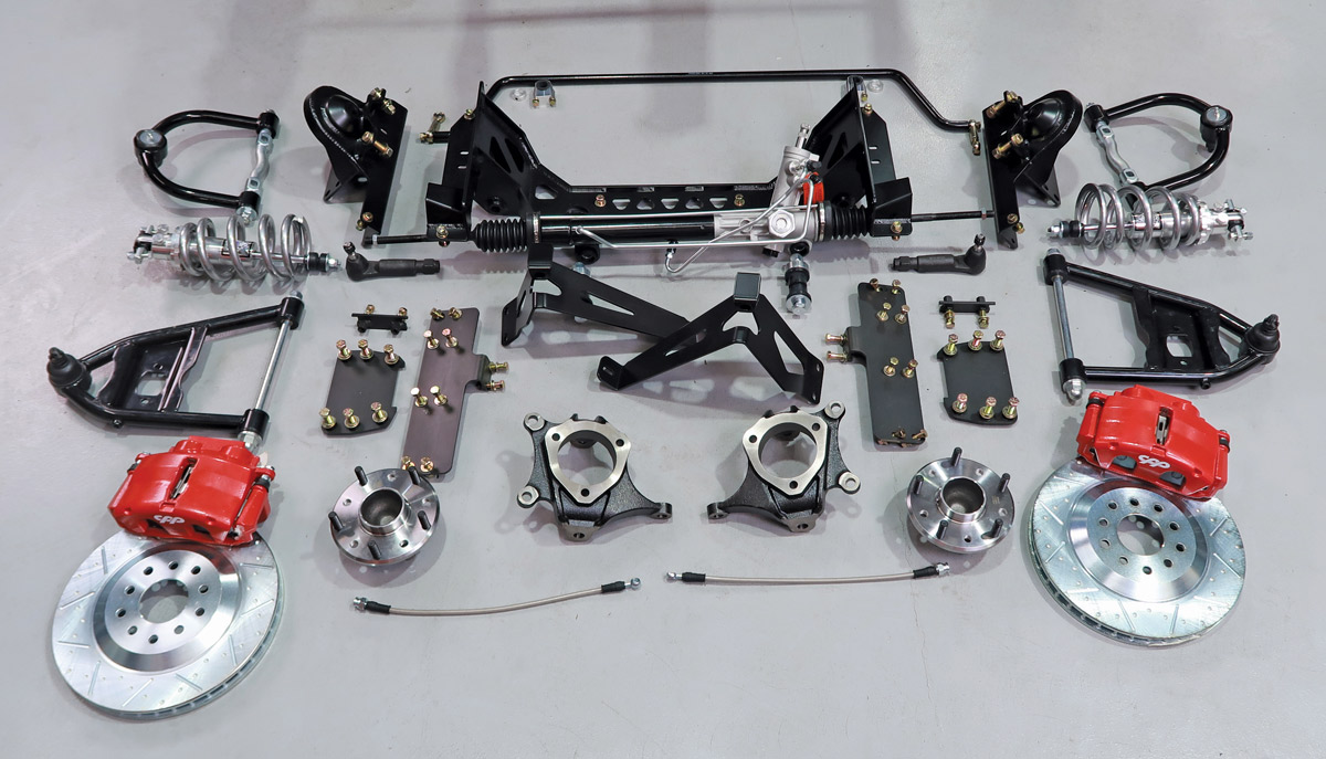
parts from CPP’s new Mustang II IFS kit on a grey surface
2. CPP’s new Mustang II IFS kit (PN E6579M2IFS) comes with coil springs and gas shocks, modular spindles with bolt-on caliper brackets, and 11.75-inch Performance Brake components.
other car part variations from CPP’s new Mustang II IFS kit
3. A variety of front suspension upgrades are available for the Mustang II IFS kits, including coilovers, C7 Corvette-style spindles with cartridge wheel bearing assemblies, and larger brakes.
metal brace installed between framerails
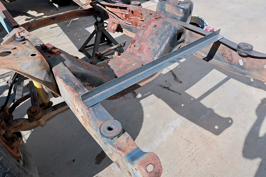
4. Before removing the stock crossmember, axle brackets, and axle mounts, a temporary brace was installed to maintain the alignment of the framerails.
closeup of yellow tape measurer and hand holding black marker up to crossmember
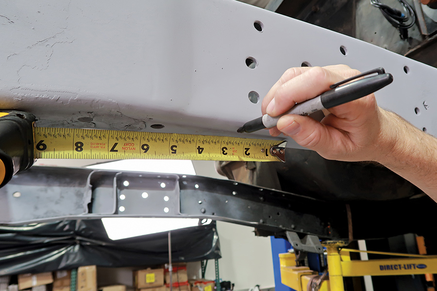
5. Other than removing the stock crossmember and associated brackets, the only modification to the ’rails is cutting a notch for the rack-and-pinion steering. The notch starts 2-1/2 inches forward from the bottom crossmember hole.
closeup of notch cut out of crossmember
6. Here the notch has been cut and the CPP crossmember has been put in place. Note all the holes in the side of the framerails. They will be used to secure the crossmember and upper control arm brackets.
closeup of hand holding nut plate
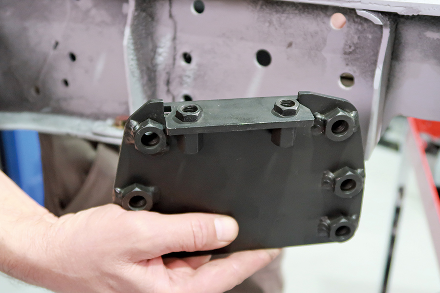
7. This is one of the nut plates that fits inside the framerails—the control arm brackets and engine mount brackets will bolt to them.
nut plate installed on framerail
8. Here the left side nut plate is positioned inside the framerail.
closeup of upper control arm/spring pocket assembly is bolted through framerail
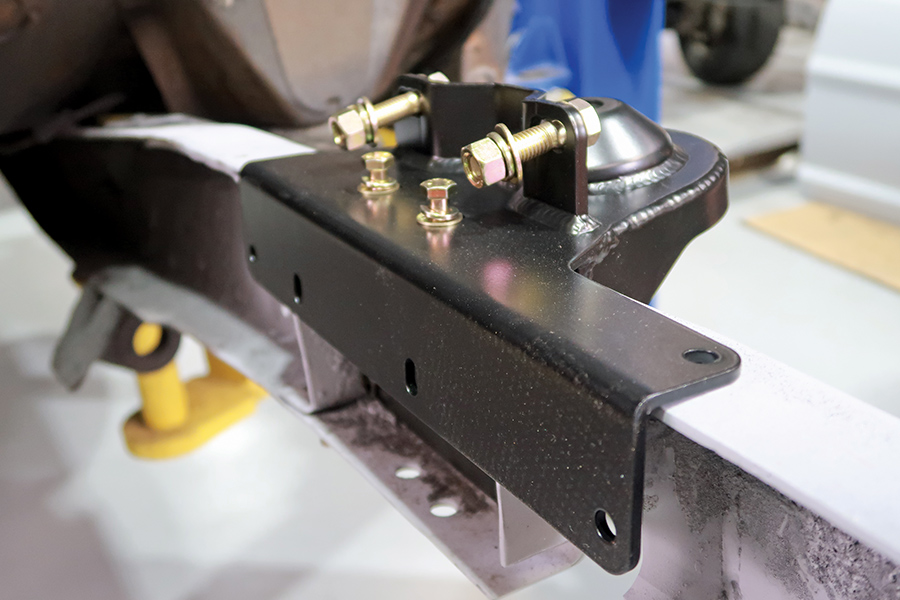
9. With the nut plate positioned the upper control arm/spring pocket assembly is bolted through the framerail into the nut plate.
closeup of control arm/spring bracket
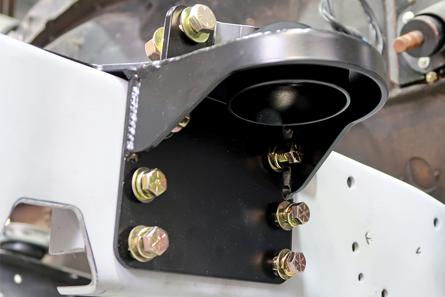
10. As can be seen in this view, the control arm/spring bracket wraps over the top of the framerail.
arms holding crossmember nut plate
11. This is the crossmember nut plate that fits behind the control arm bracket.
both nut plates installed to keep crossmember and control arm brackets together
12. The nut plates on each side serve to tie the crossmember and the control arm brackets together for strength. All fasteners are Grade 8.
hand tightening bolt
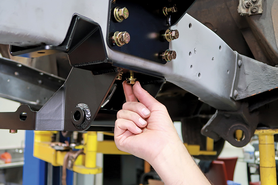
13. A pair of additional bolts through the bottom of the crossmember on each side help secure the crossmember to the nut plates. It’s best to install all the bolts first then tighten them all.
person drilling holes into framerail
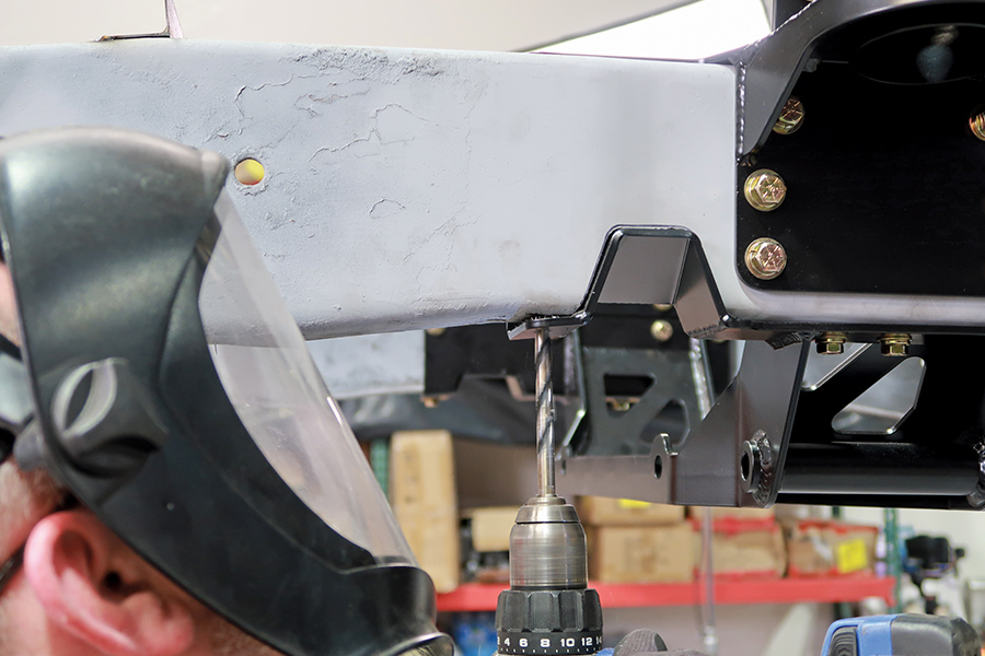
14. On each side of the steering notches a total of four holes are drilled in the framerails to help secure the crossmember.
hands drilling holes meant to fit bolts
15. The final two of the six holes required are for bolts on each that go through the upper brackets and the framerails.
sparks coming from hand using circular saw to remove brace between framerails
16. Once the crossmember is in place the temporary brace can be removed.
finished crossmember installation
17. The finished crossmember installation is clean, simple, and extremely strong.
man using tool in lower control arms
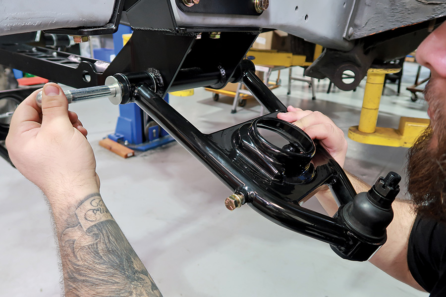
18. CPP’s tubular lower control arms come with urethane bushings and black powdercoating.
hand holding rack-and-pinon steering gear
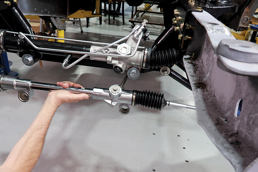
19. A new power or manual rack-and-pinon steering is part of the kit—the price is the same for either type.
hands holding coil spring
20. When installing the coil springs a spring compress is strongly recommended to keep them from popping out unexpectantly.
hands holding upper control to vertical plate
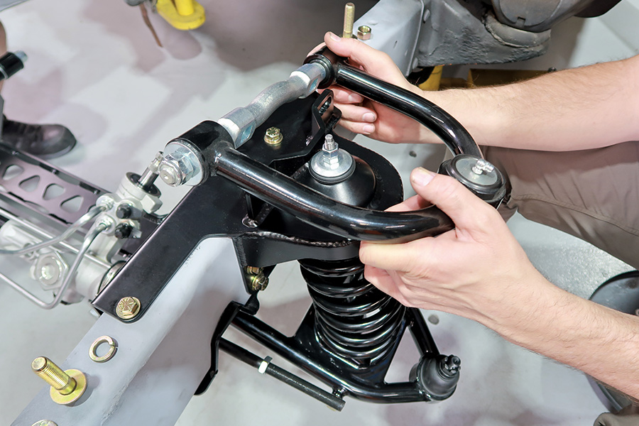
21. The upper control arms bolt to vertical plates and use shims for camber adjustment. A series of three attachment holes allow the upper control arm to be moved fore and aft to provide caster adjustment options.
drop spindle
22. CPP offers stock and dropped spindles, both use bolt-on caliper brackets.
hub and rotor combination
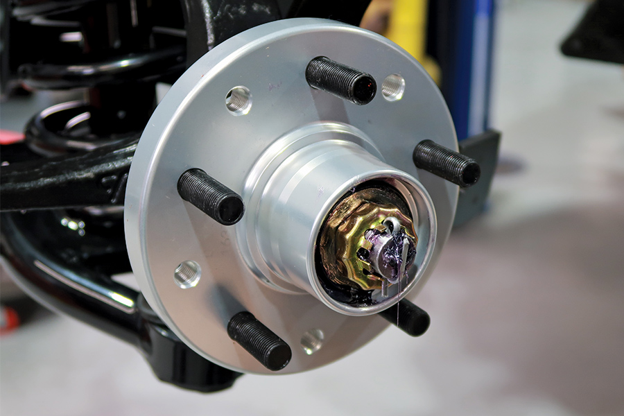
23. CPP offers three different hub and rotor combinations: 5-on-4.5 and 5-on-4.75 (shown), 5-on-5 and 5-on-5.5, and 6-on-5.5.
man installing piston
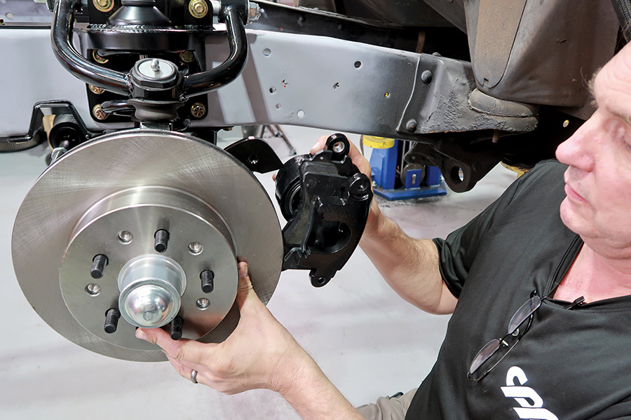
24. CPP’s standard performance brake package includes S-10–style calipers with big bore pistons for excellent stopping power.
closeup of sway bar
25. The 3/4-inch sway bar attaches to the lower control arms with adjustable links.
closeup of sway bar secured to crossmember
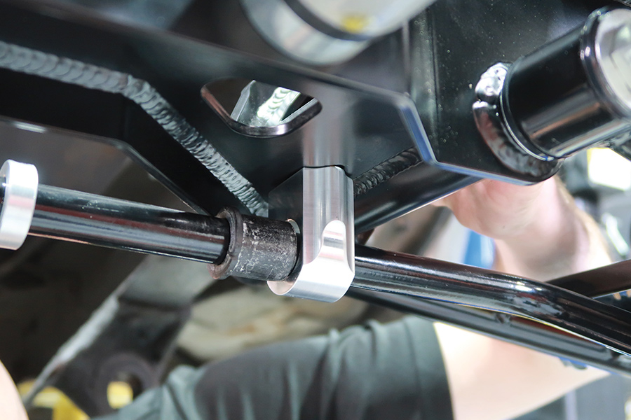
26. Securing the sway bar to the crossmember are billet aluminum brackets.
hand installing tie-rod ends
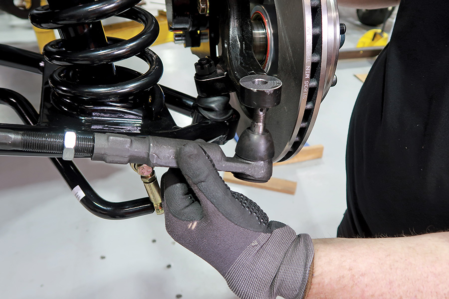
27. With the suspension assembled, the tie-rod ends are installed. Needless to say the truck’s first trip will be to an alignment shop.
completed front suspension installation with the engine mount brackets in place
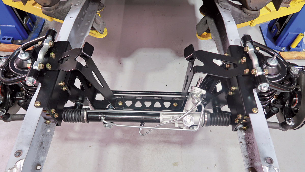
28. The completed front suspension installation with the engine mount brackets in place. Note they attach to the upper bolts that also secure the control arm brackets.
CPP’s FitRite mounts
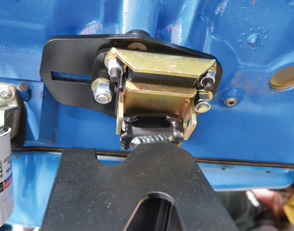
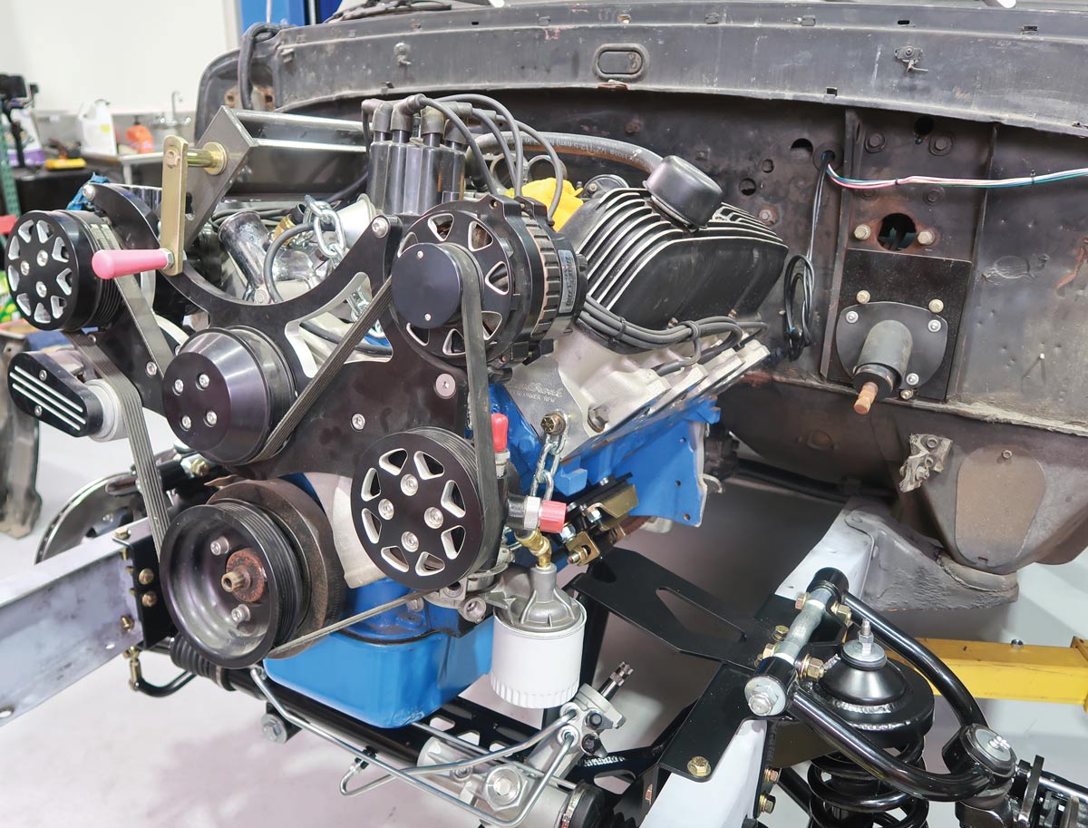
29. From the “why didn’t I think of that department,” CPP’s FitRite mounts allow the engine position to be to be moved to the front or rear of the chassis a total of 3 inches for the best fit.
FE Ford engine with mounts
30. In this case the engine of choice is an FE Ford, however mounts are available for a variety of Ford and Chevrolet engines.
SOURCE