CTP logoFeature star Tech
InTheGarageMedia.com
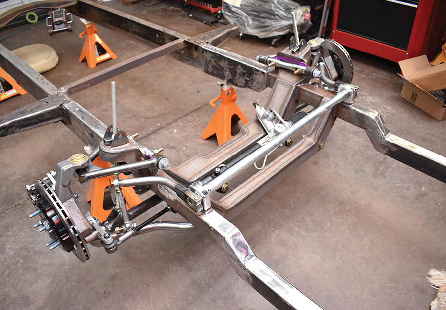
The author (left) and Paul Willis (right) put the finishing touches on the G-Comp front suspension installation on a 1955 Ford F-100 frame.
Double Duty
Fixing a Fouled Up Frame and Installing Speedway Motors’ G-Comp Front Suspension
BY Ron CeridonoPhotography BY The Author
T

his saga started not long after our good friend, Paul Willis, announced he had unequivocally finished his last project truck. Shortly thereafter Willis brought home a 1954 Ford F-100 that he claimed would really be his last project.

Like many trucks its age, this latest acquisition had undergone several modifications—the most notable being the once-popular installation of a Volare transverse torsion bar front suspension. This swap included a failed attempt at adding a rack-and-pinion steering gear of unknown origin and a pair of crudely fashioned motor mounts. It all had to go.

As was often done with such installations, the bottom lips of the Ford’s framerails were cut away, then the complete Mopar crossmember was welded in place. That meant to install a more suitable independent front suspension system the Volare crossmember would have to be cut out, after which the framerails would require major repairs.

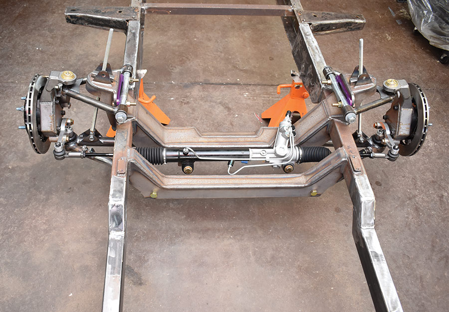
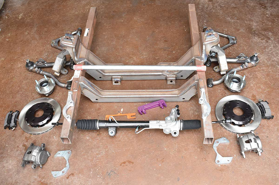
When it comes to selecting a replacement IFS for the Ford there are a variety of kits to choose from, but one of the most intriguing is Speedway Motors’ G-Comp Universal front suspension system. Not another version of the Pinto/Mustang II design that’s been done over and over, the G-Comp Pro Touring style frontend is a complete assembly based on a subframe made from 2×3-inch, 0.120-inch wall tubing. Available in 56-, 58-, 60-, and 62-inch track widths, 56- and 58-inch versions are 29.75 inches wide at the outside of the framerails, while the 60- and 62-inch versions are 33.75 inches at the outside of the rails.

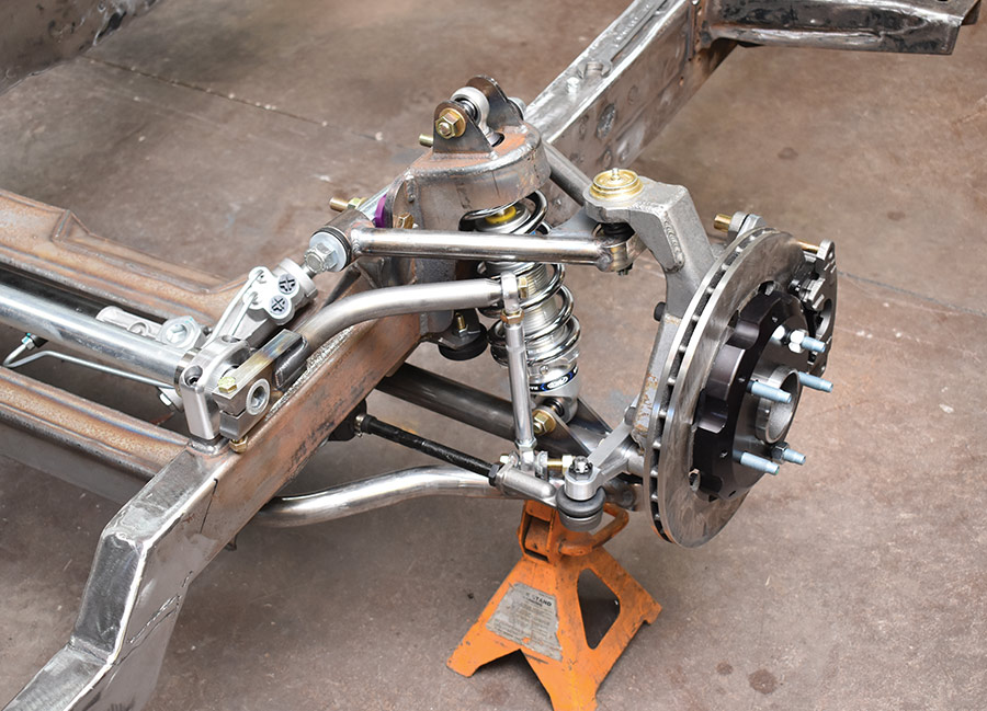
The G-Comp suspension comes with Speedway’s exclusive G-Comp uprights that use Corvette-style cartridge spindles. Engineered for optimum handling and vastly improved control, the G-Comp’s suspension geometry provides optimized camber gain for better handling and no bumpsteer. To provide the ultimate in suspension tuning options camber adjustments are made with shim plates and caster changes are made with inserts in the upper cross shafts—both are more secure than the slotted adjustment holes often found in Mustang II kits. Also included in the G-Comp IFS kits are a power rack-and-pinion steering and a 1&frac14 inch od splined sway bar (coilovers are sold separately).

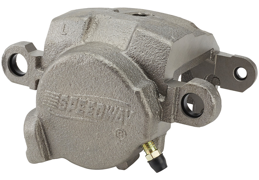
The G-Comp front suspension is designed to use C6 Corvette-style brakes, such as the Wilwood PN 835-1408921 with 13-inch rotors and Superlite 6R six-piston calipers. Another option is Speedway’s Economy disc brake kit (PN 3502001) that uses their own GM metric-style calipers and Pro-Lite brake rotors. It will work with 15-inch steel wheels and 16-inch and larger aftermarket wheels.

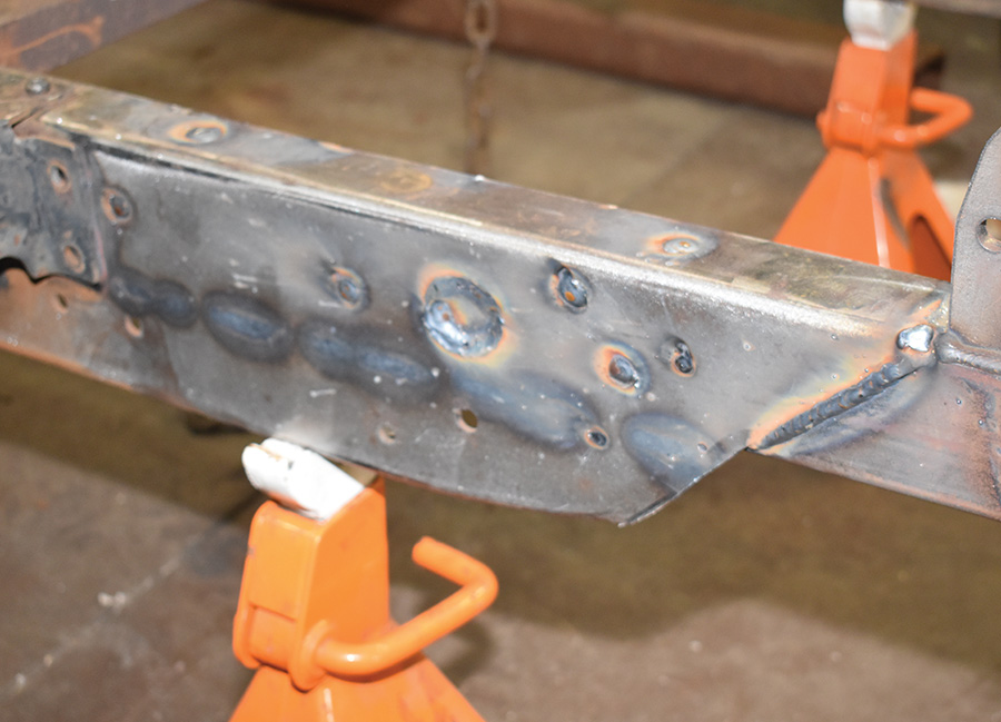
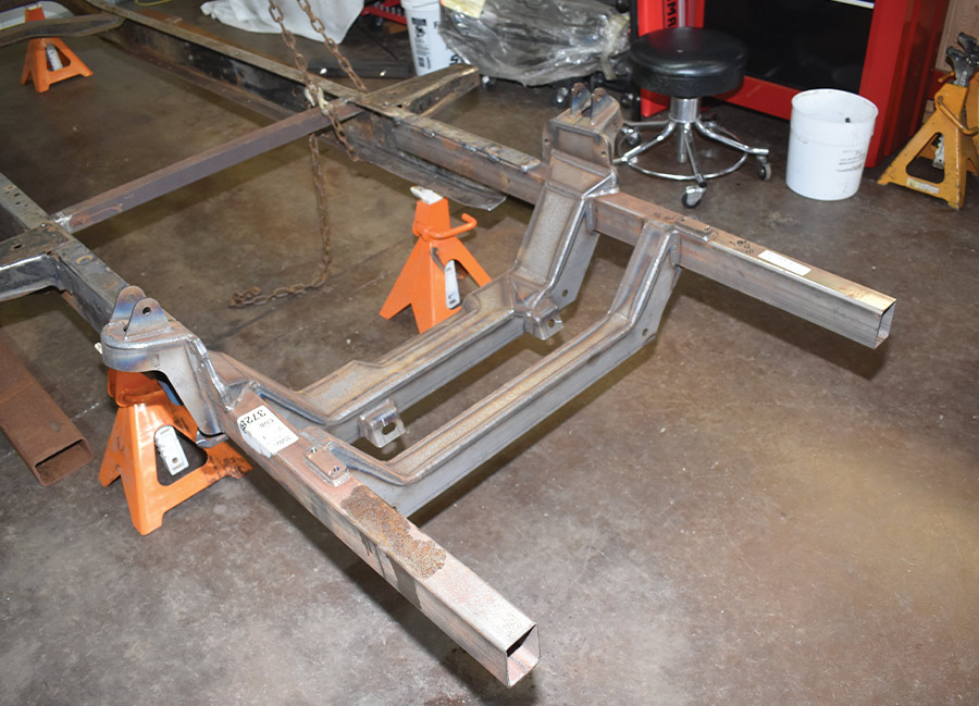
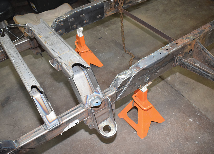
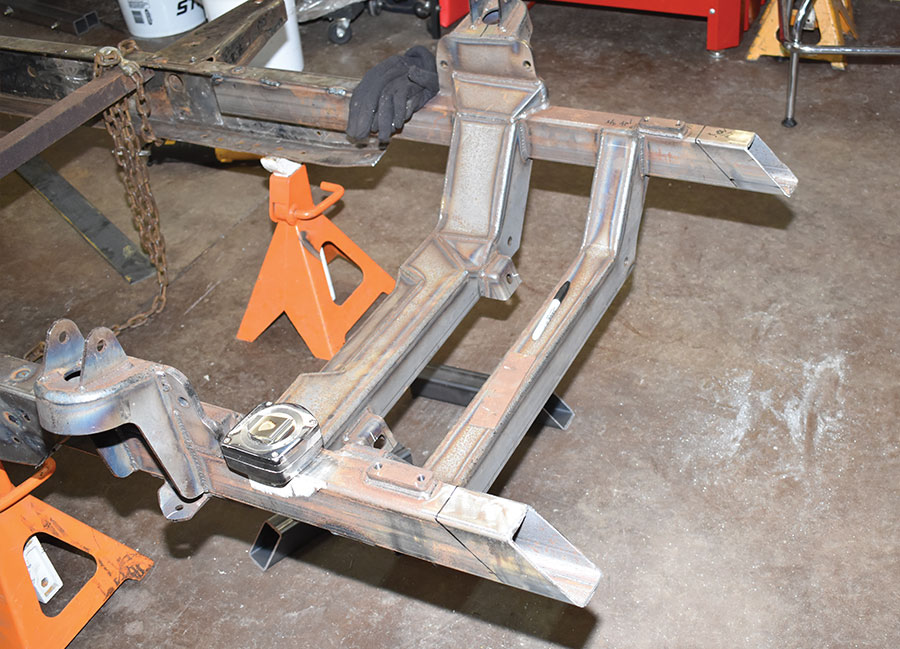
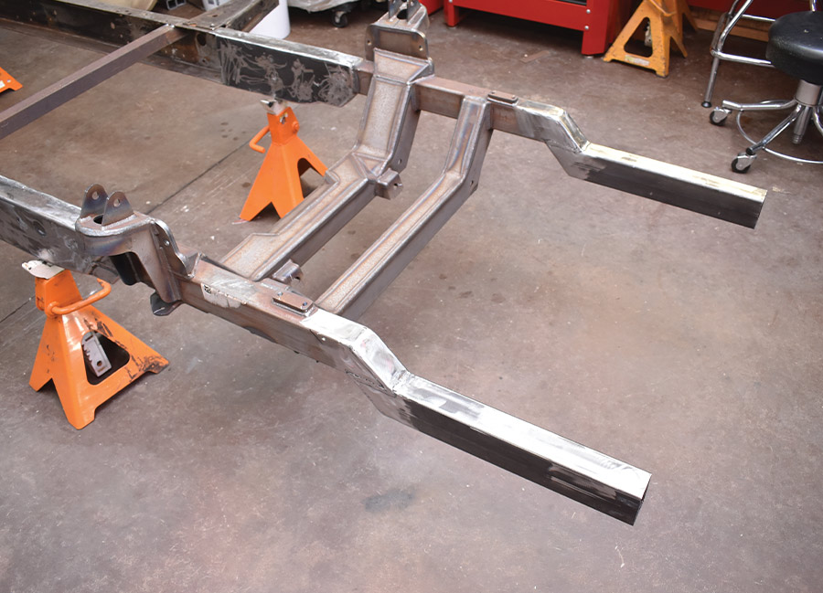
With the Volare frontend removed, we simply cut off the damaged portion of the Ford’s frame then slipped the Speedway subframe inside the remaining portion of the ’rails. With the subframe in place it was thoroughly welded to the original frame and then the areas where the two were joined were boxed. In our case the only additional modifications were to add portions of rectangular tubing to the front of the subframe to provide mounts for the stock bumper.

Speedway’s G-Comp suspension is the ideal update for the front suspension under almost any classic truck. For us it fixed our fouled up frame and provided our F-100 with a truly state-of-the-art suspension system—we call that a win on both counts.
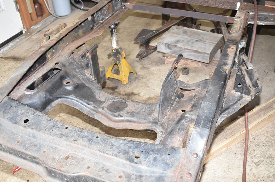
The stock frame
1. This is what we started with. The stock frame had been notched and then a Volare crossmember was welded in place.
Speedway Motors’ G-Comp subfame assembly
2. Our choice for a replacement front suspension system was Speedway Motors’ G-Comp subfame assembly. The width is 60 inches wheel flange to flange and the subframe measured 33.75 inches to the outside of the rails.
A reciprocating saw
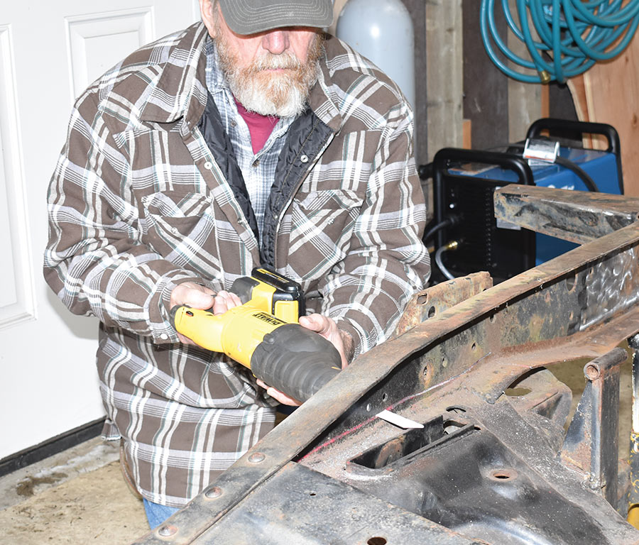
3. A reciprocating saw was used to remove the Mopar front crossmember that had been arc welded in place. The bottom flanges of the framerails had been cut off during the original suspension swap.
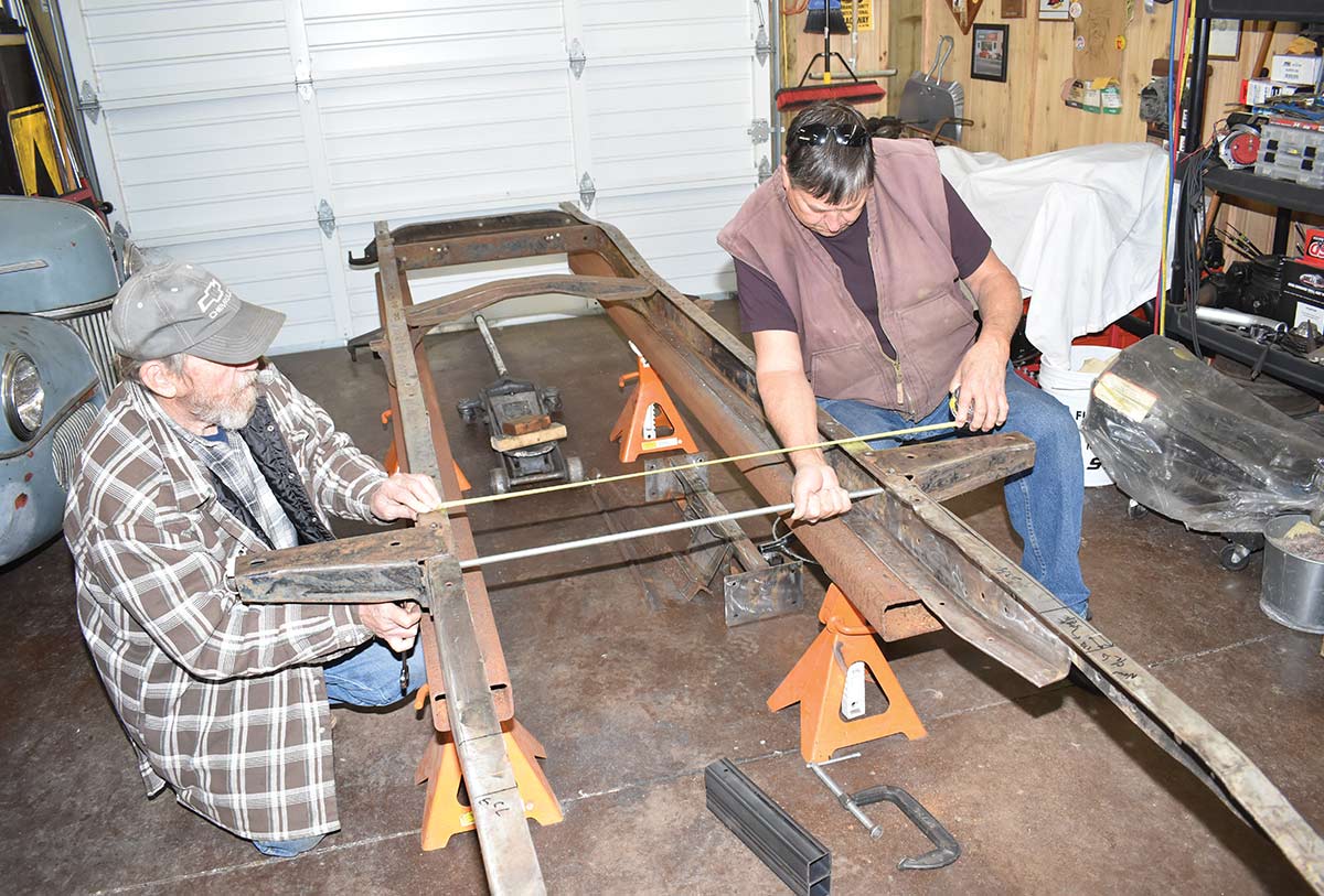
the frame resting on leveled lengths of heavy steel tubing

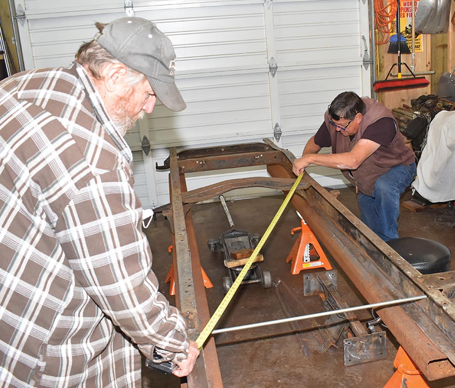
4. With the frame resting on leveled lengths of heavy steel tubing, a pair of Pauls (Willis on the left and Wilson on the right) measured it diagonally from several points. Satisfied the frame was “square,” it was clamped to the tubing that acted as a makeshift jig.
the framerails had bowed out slightly
5. As a result of having the original crossmembers removed, the framerails had bowed out slightly. We pulled them together with a length of threaded rod to the factory measurement of 34 inches. We’ll be adding a new X-member.
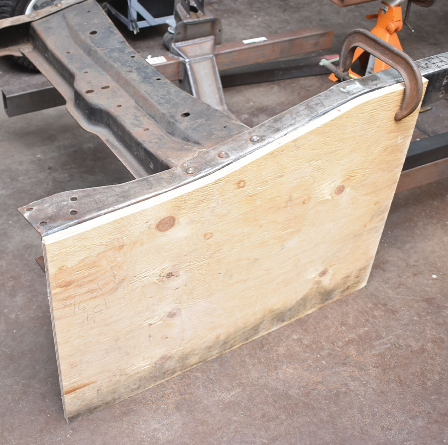
the F-100 frame drops down 23/4 inches
6. Up front, the F-100 frame drops down 2¾ inches to accommodate the radiator core support and the bumper mounts. We made a plywood template so we could duplicate the locations of both.
the centerline
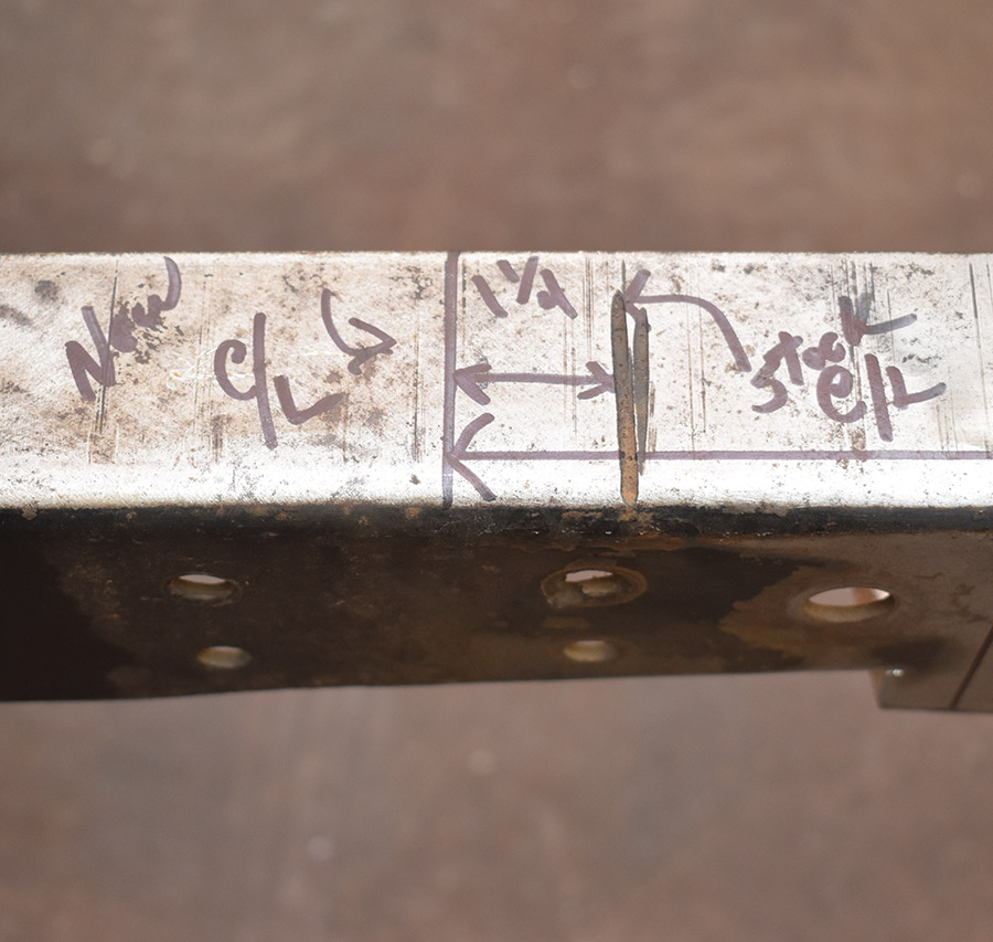
7. To the centerline of the original front axle was determined from a factory blueprint. In stock form the front wheels are too far back in the fenders; we moved them forward 1¼ inches to center them in the openings.
frame was to be cut 23¹/8 inches forward of the front body mount
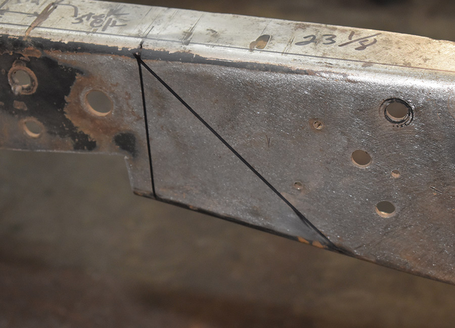
8. It was determined that the frame was to be cut 23⅛ inches forward of the front body mount. The ’rails were cut at an angle to provide more surface for welding.
The G-Comp subframe
9. The G-Comp subframe was the perfect width to slip inside the Ford frame. It was then welded at each end, skip welded along the bottom of the tubes on the inside of the frame, and rosette welds were made through the factory holes in the ’rails.
G-Comp subframe extended inside the ’rails
10. The G-Comp subframe extended inside the ’rails almost to the front body mounts. The area was boxed with a ⅛-inch plate with holes for rosette welds.
We flipped the frame upside down
11. We flipped the frame upside down and welded 2×2-inch tubing in place to fill the void between the subframe and the Ford’s framerails.
extensions were made from 2x3 tubing
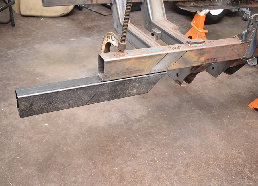
12. To drop the front of the frame to accommodate the radiator core support bumper extensions were made from 2×3 tubing.
the subframe was cut at an angle
13. The front of the subframe was cut at an angle, the bottoms of the tubes were then trimmed to 2¾ inches so the extensions would be at the correct height.
the open ends of the tubing were capped
14. After the new extensions were welded in place the open ends of the tubing were capped.
The lower control arms
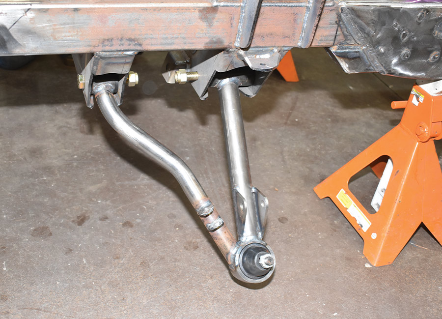
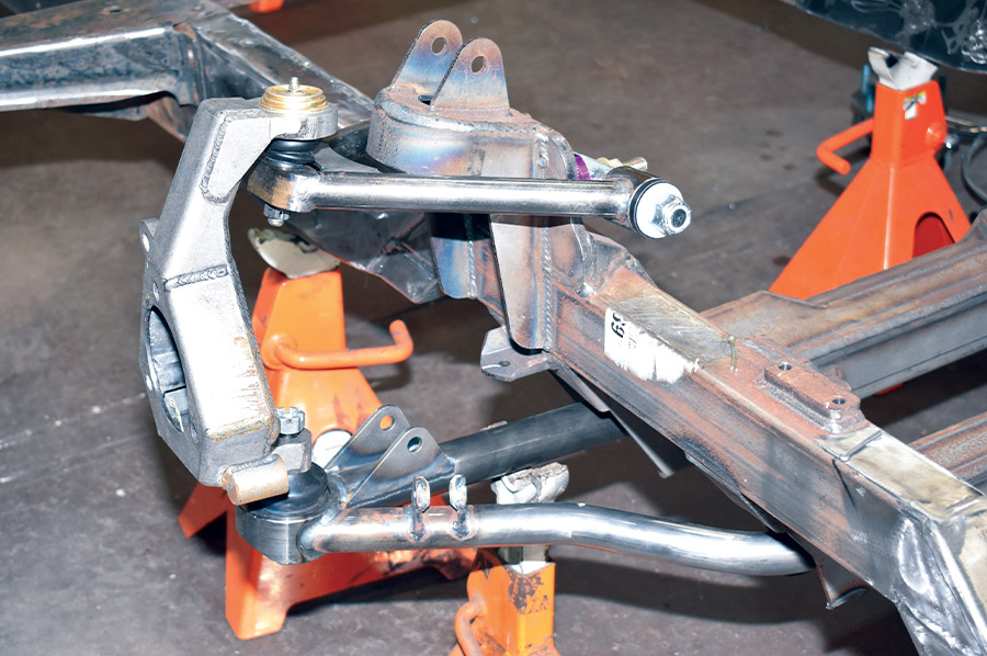
15. The lower control arms have a recessed front strut to increase tire clearance. They come equipped with heavy-duty ball joints and Delrin bushings.
adjustments are made with shims between the upper cross shaft and the spring tower
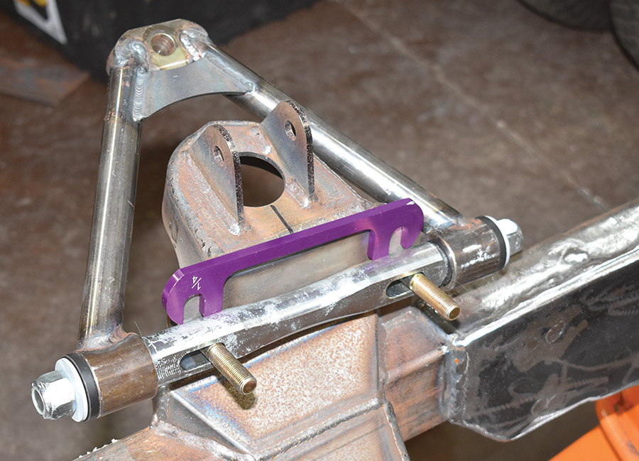
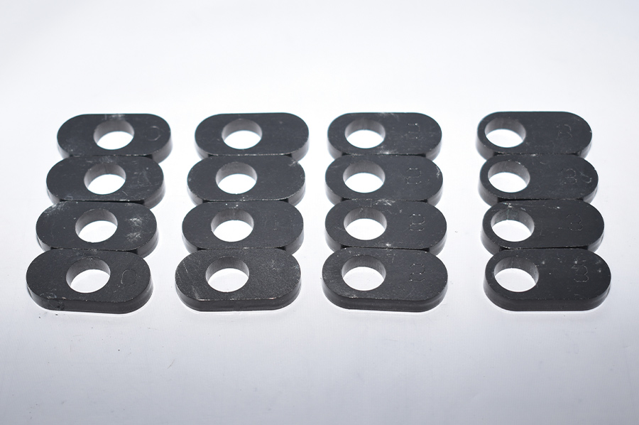
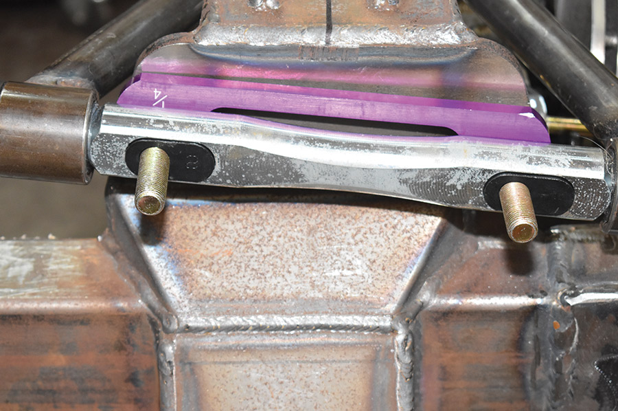
16. For camber adjustments that can’t slip, adjustments are made with shims between the upper cross shaft and the spring tower. A selection of shims come with the G-Comp kit.
clever inserts that fit into the upper control arm cross shafts
17. Caster adjustment are made with these clever inserts that fit into the upper control arm cross shafts. Eight settings are available from centered to full limit in ⅛-inch increments.
the caster inserts fit into slots in the zinc-plated steel cross shafts
18. The caster inserts fit into slots in the zinc-plated steel cross shafts. They’re held in place by the lock nuts that secure the shafts.
Speedway’s fabricated spindle uprights
19. Speedway’s fabricated spindle uprights are beautifully built and extremely strong. Note the use of inverted upper ball joints to provide additional wheel clearance.
G-Comp uprights accept AC Delco original equipment
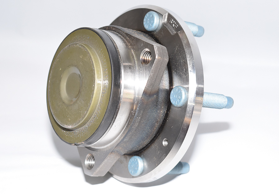
20. The G-Comp uprights accept AC Delco original equipment wheelhubs and bearing assemblies (PN FW412). They are sealed with lifetime lubrication.
Three socket head capscrews secure the hub
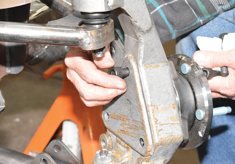
21. Three socket head capscrews secure the hub and bearing assembly to the upright.
Speedway’s rotors attach to the hubs with socket head screws
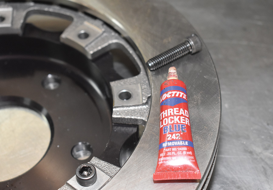
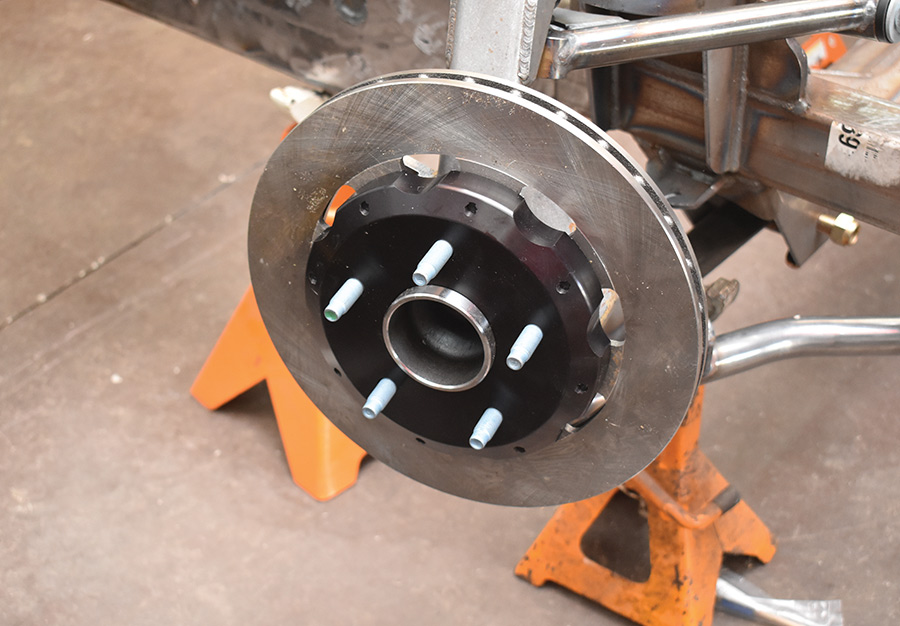
22. Speedway’s rotors attach to the hubs with socket head screws, which should have thread locker applied during installation.
fasteners drilled for safety wire
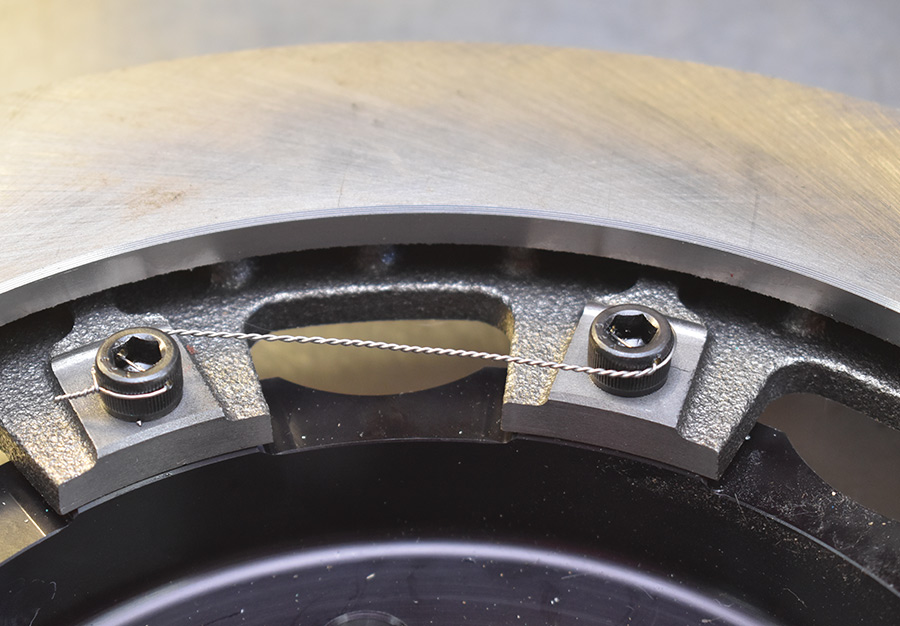
23. An option when assembling the hubs and rotors are fasteners drilled for safety wire. We wired them in pairs (note if one loosens it tightens the other). Drilled fasteners are available from Speedway.
Speedway’s Pro-Lite vented brake rotors
24. Speedway’s Pro-Lite vented brake rotors are cast from premium grade, long-grain carbon iron, which exhibits long wear, high thermal stability, and excellent resistance to distortion in high-heat situations.
The economy C7 disc brake kit
25. The economy C7 disc brake kit includes brackets that accept Speedway’s GM metric-style calipers with 2.375-inch single pistons.
Speedway metric calipers
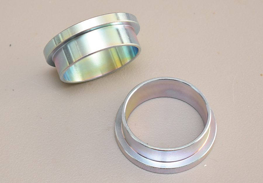
26. To use the Speedway metric calipers with the Pro-Lite rotors these brake pad spacers are required. They fit inside the caliper’s pistons.
new power rack-and-pinion steering gear
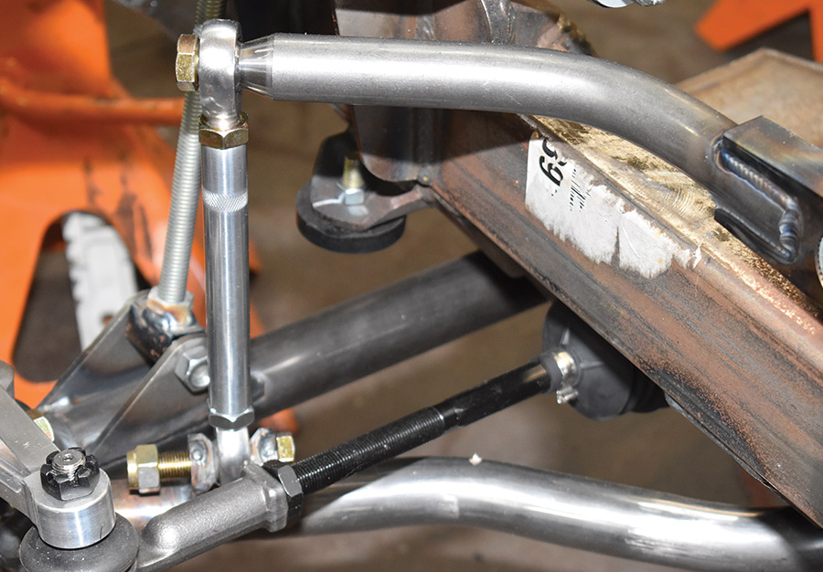
27. Included in the G-Comp kit is a new power rack-and-pinion steering gear. For mockup at ride height we made struts from threaded rod.
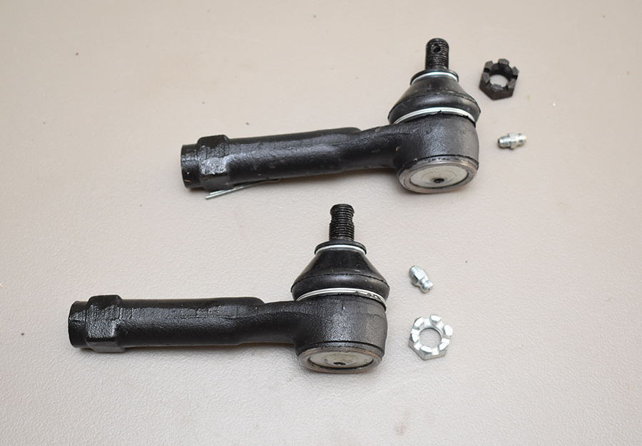
Speedway’s longer-than-stock tie-rod ends are required
28. In some G-Comp applications (such as ours) Speedway’s longer-than-stock tie-rod ends are required.
Aluminum pillow blocks
29. Aluminum pillow blocks secure the 1¼-inch tubular sway to the subframe. The splined ends accept arms that are secured with pinch bolts.
Endlinks with left- and righthand rod ends
30. Endlinks with left- and righthand rod ends connect the swap bar to the lower control arm. Note the knurls that make adjusting the links easy.
The coilovers
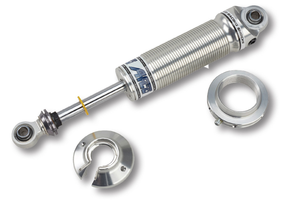
31. The coilovers are from Afco with multi-stage valving that provide excellent ride and handling characteristics with firm control over relatively slower strokes (chassis roll).
400-pound springs are recommended
32. For small-block applications such as ours, 400-pound springs are recommended; for big-blocks 500-pound springs should be used.
 SOURCE
Speedway Motors
(800) 979-0122
speedwaymotors.com