CTP  Tech

InTheGarageMedia.com

A drive toward perfection
close up of a serpentine package on an LS engine
A Clean Serpentine Package for any LS Engine
BY Ryan MansonPhotography BY THE AUTHOR
O

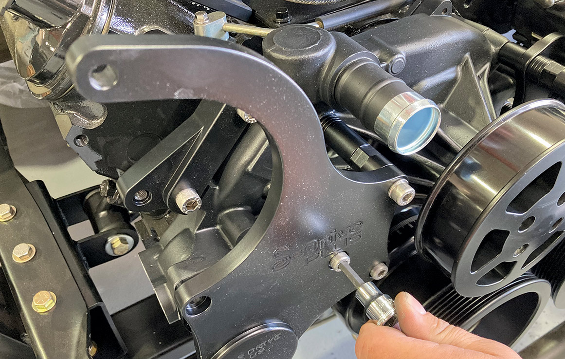
ne of the benefits of using a late-model engine, such as the venerable LS-series of GM powerplants, is the fact that they came equipped from the factory with a reliable, serpentine belt setup. Unlike the V-belt systems of old, the serpentine-style requires reduced belt tension, resulting in less stress on the various components’ bearings and seals and increased belt-to-pulley contact ratio, resulting in less belt slippage. Reliability in the upper-rpm range is also a benefit of the serpentine belt design over the old V-belt. Unfortunately, the packaging of many OE serpentine systems can leave something to be desired, not to mention their rather utilitarian appearance. When it comes to building a custom truck with a tidy engine compartment, a stock pulley system just doesn’t cut it. Thankfully, Eddie Motosports (EMS) saw the writing on the wall when they introduced their line of S-Drive serpentine pulley systems a few years back and successfully filled the void.

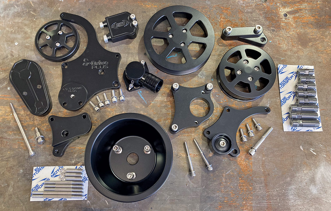
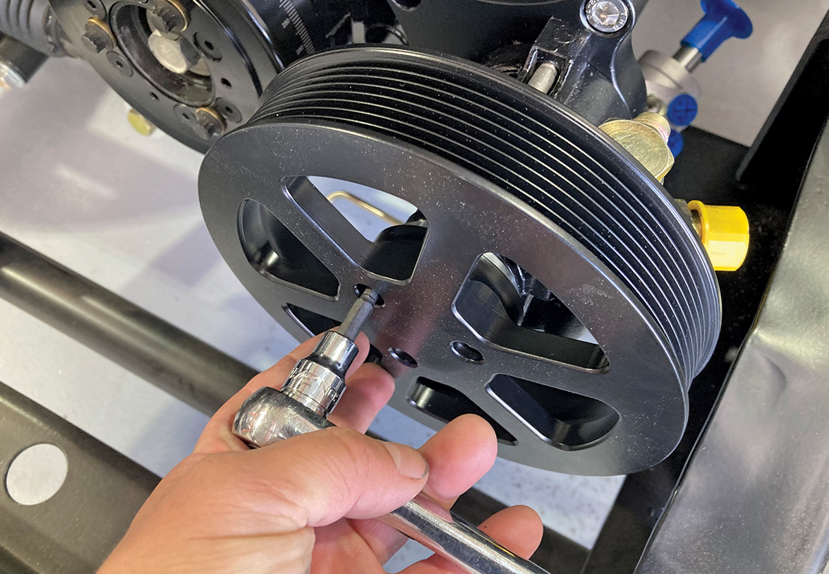
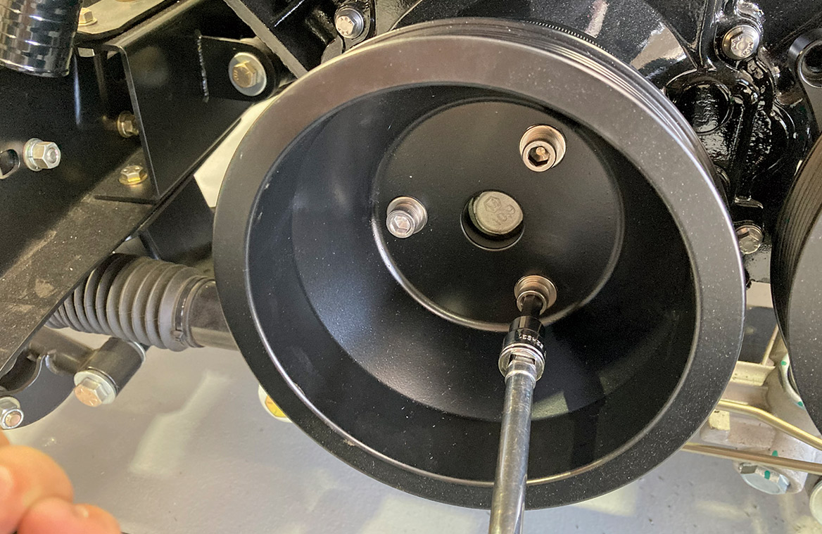
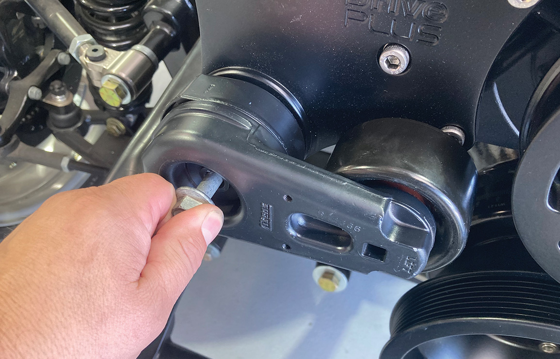
Since then, EMS has continued to improve upon the S-Drive product line by introducing an eight-rib version in an effort to reduce belt slippage in high performance applications. Their latest offering, dubbed the Pro Touring Kit, expands upon that performance aspect by utilizing not only an eight-rib belt and pulley setup but an additional idler pulley for increased belt wrap on the alternator and power steering pulleys. An oversized pulley on the power steering pump helps slow the pump down during high-rev maneuvers on the autocross track.

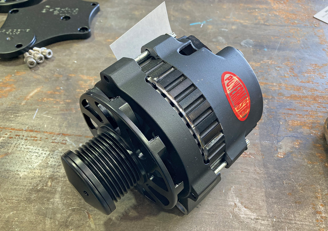
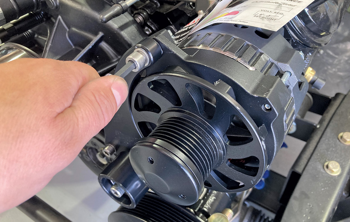
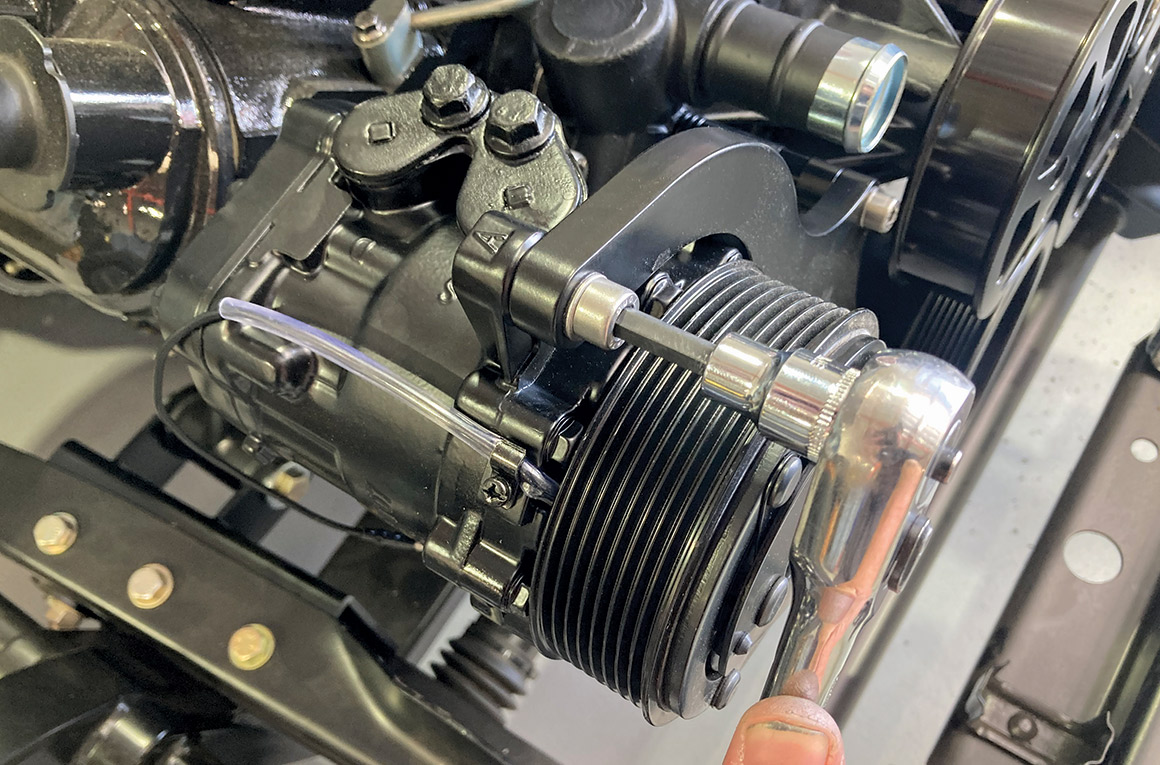
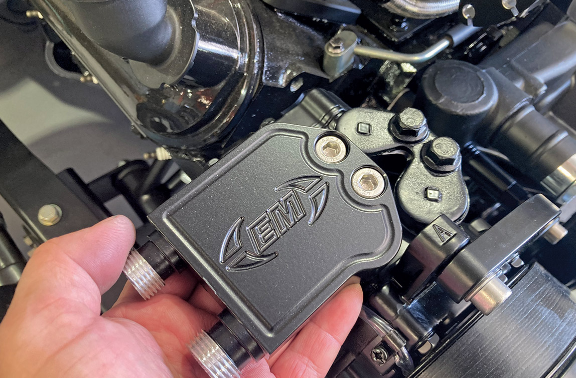
But a tight package was only one of EMS’s goals when it came to designing a clean-sheet drive system. Appearance would also be a key factor, so the team knew that they’d need to design a kit that looked as good as it performed, available in several different finishes to boot. But even more important was the performance aspect of the kit, not only as a whole but as it pertains to the individual components as well. To that end, EMS teamed with some of the most respected names in the industry to provide the individual components, such as Tuff Stuff/PRW for the water pump and Powermaster for the alternator of every kit they manufacture. This ensures that not only will the kit function as advertised, it will do so over a wide swath of performance variables for a long time to come.

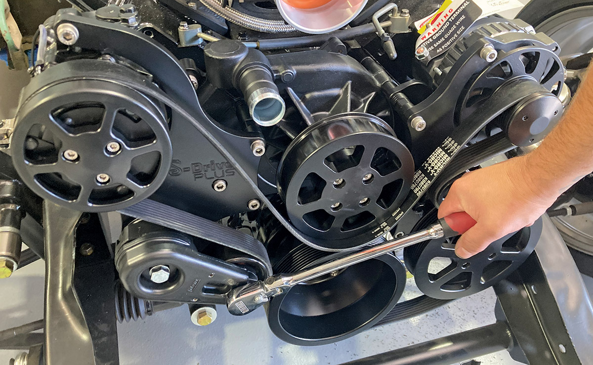
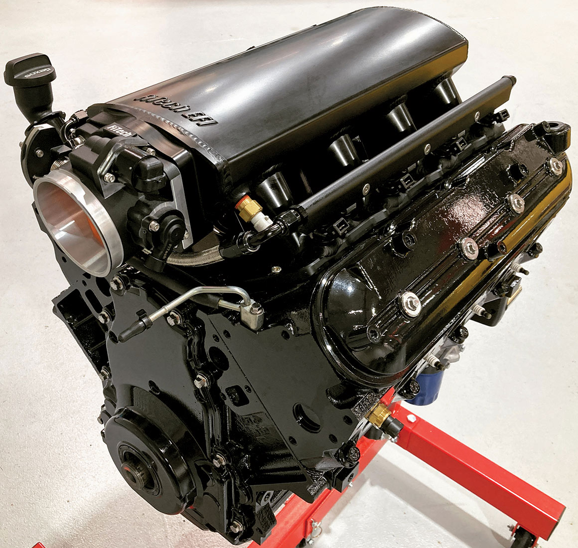
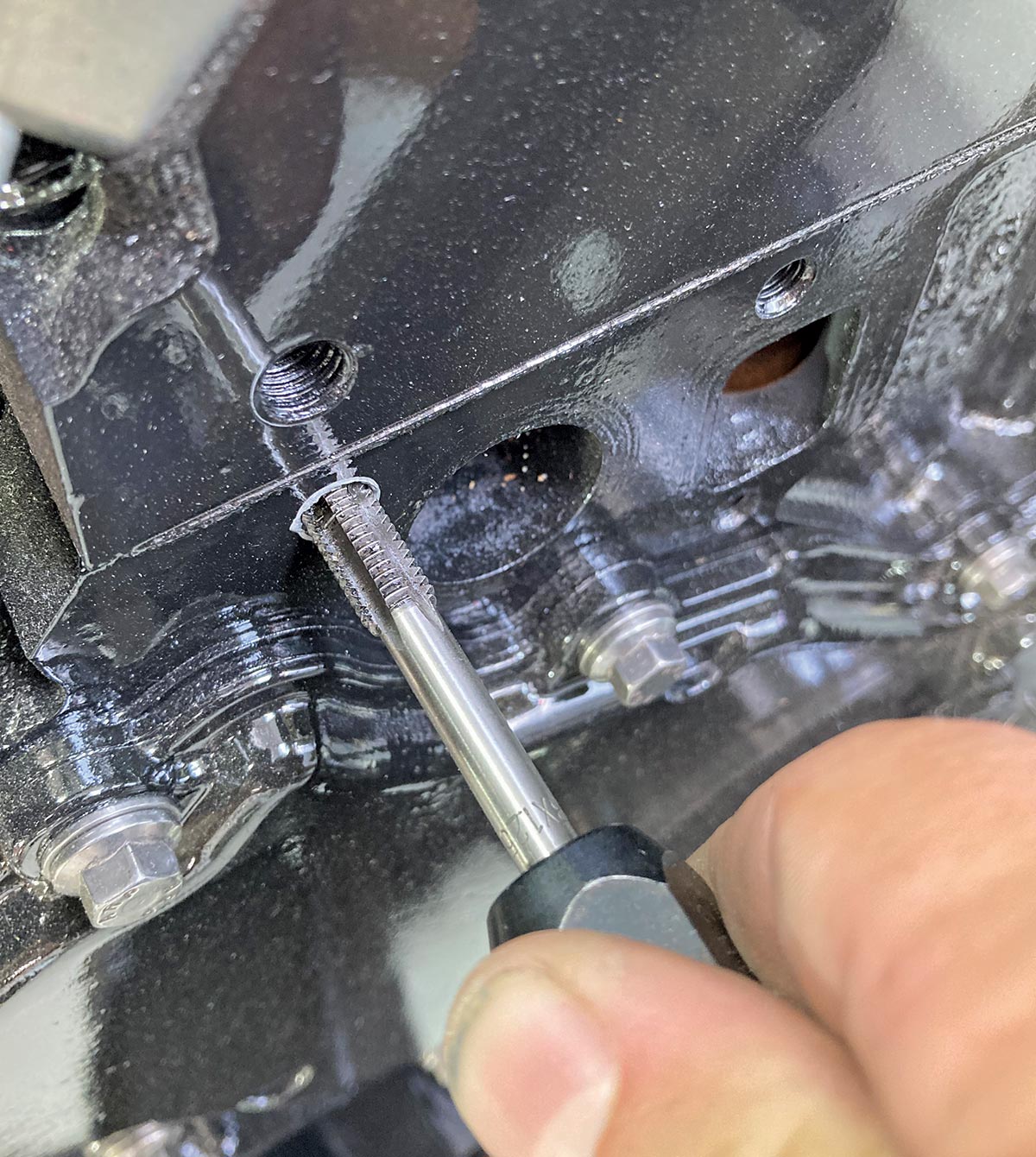
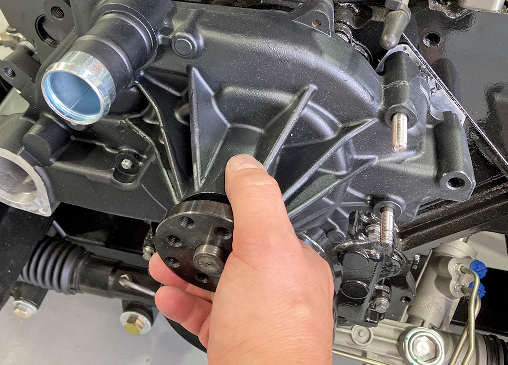
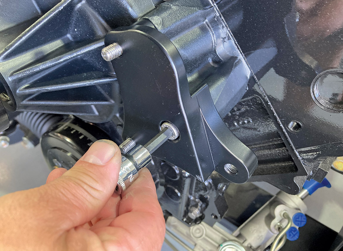
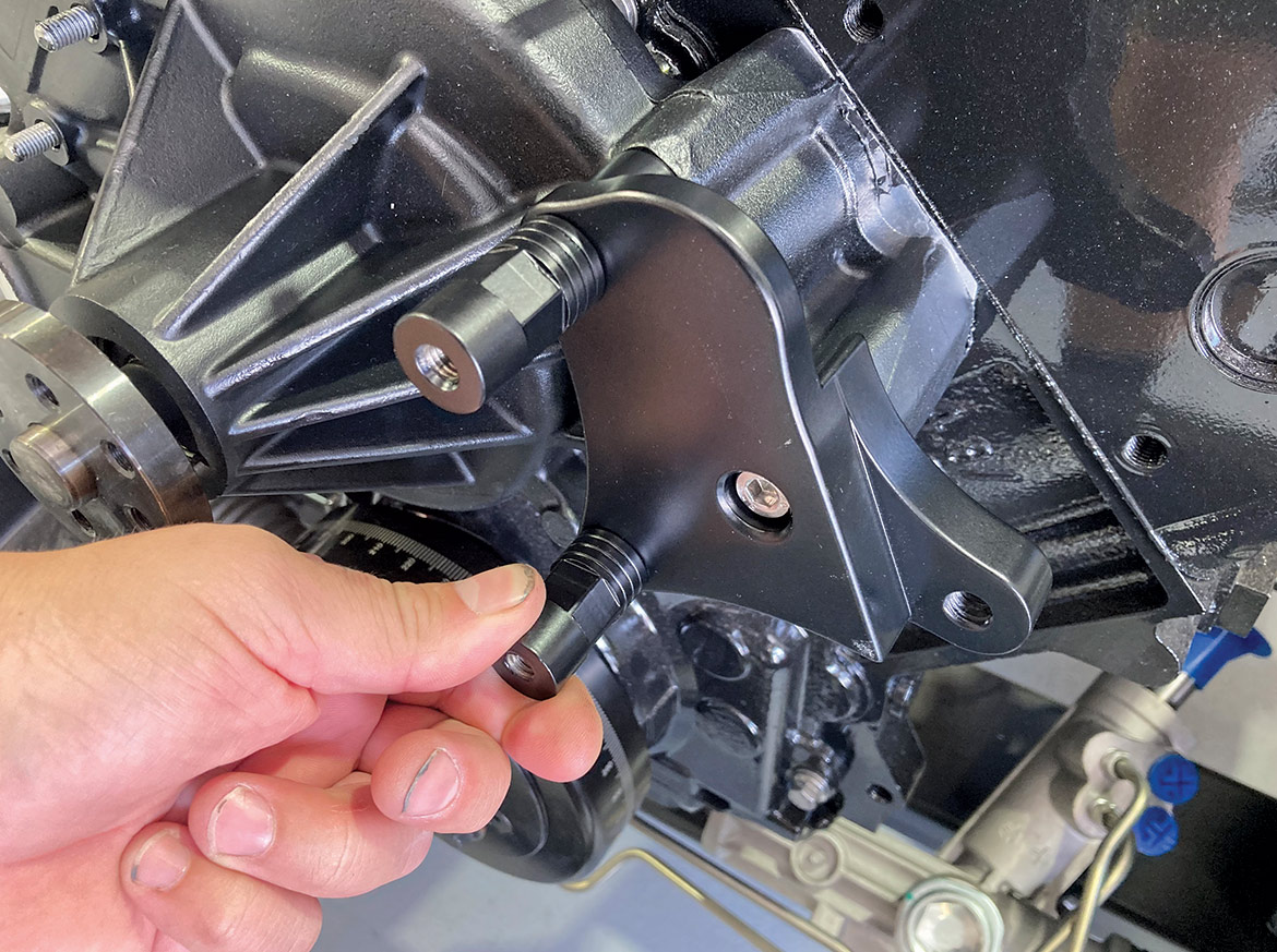
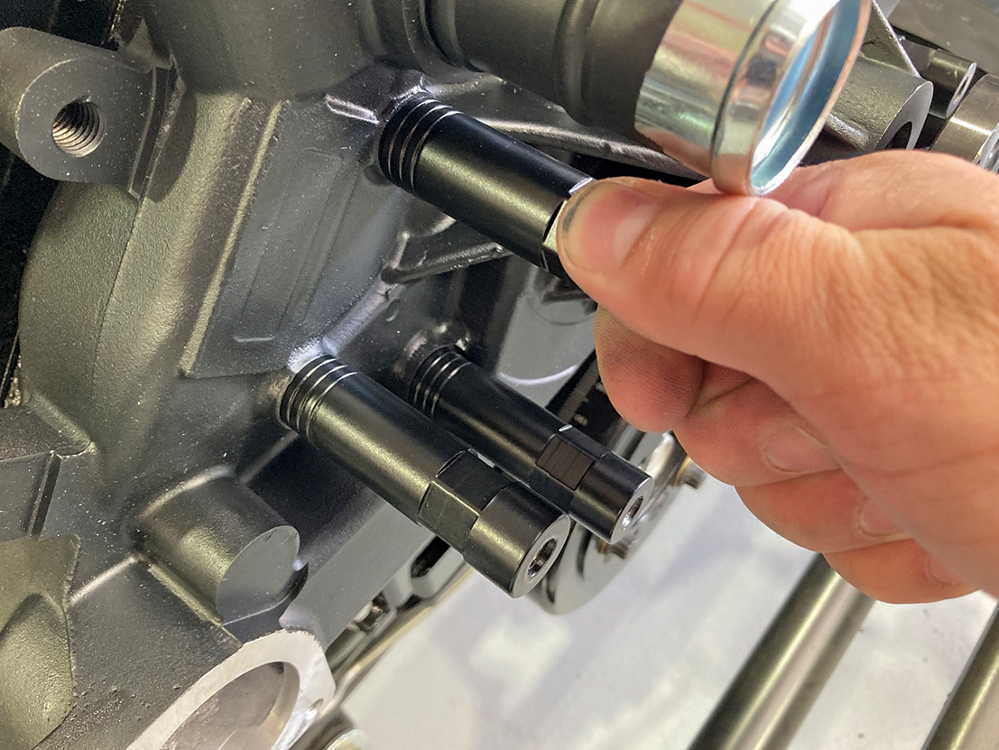
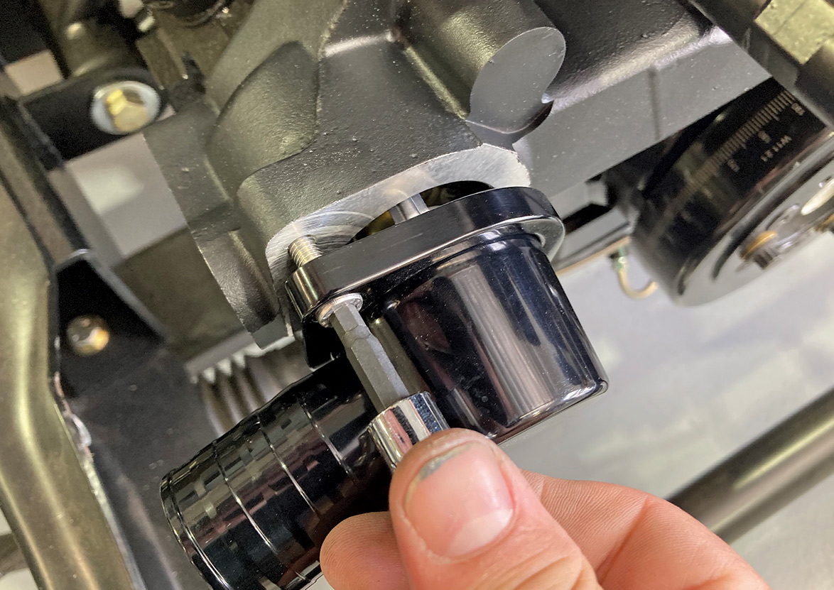
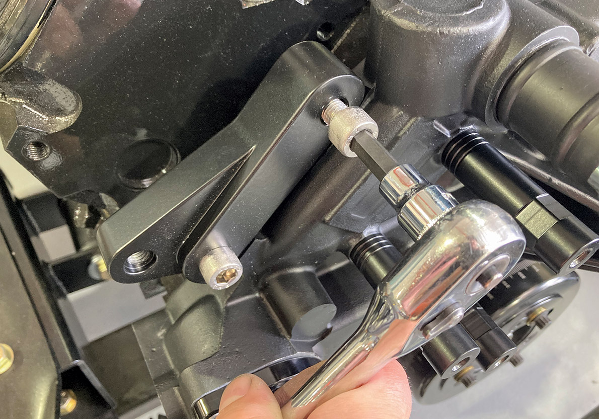
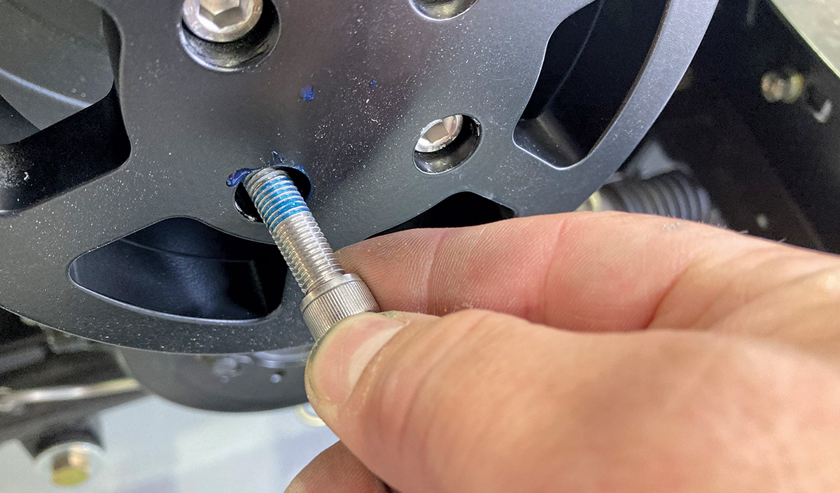
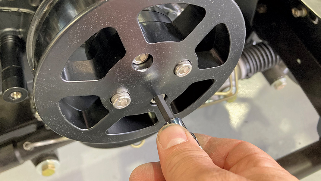
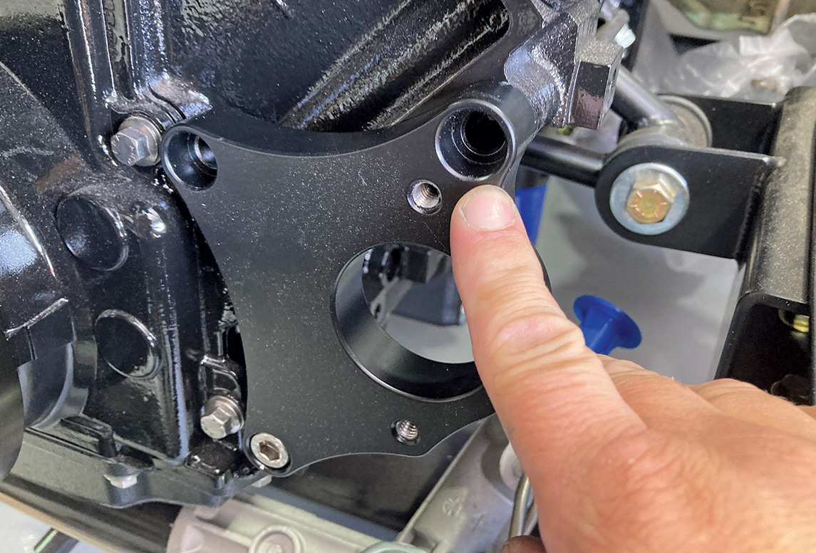
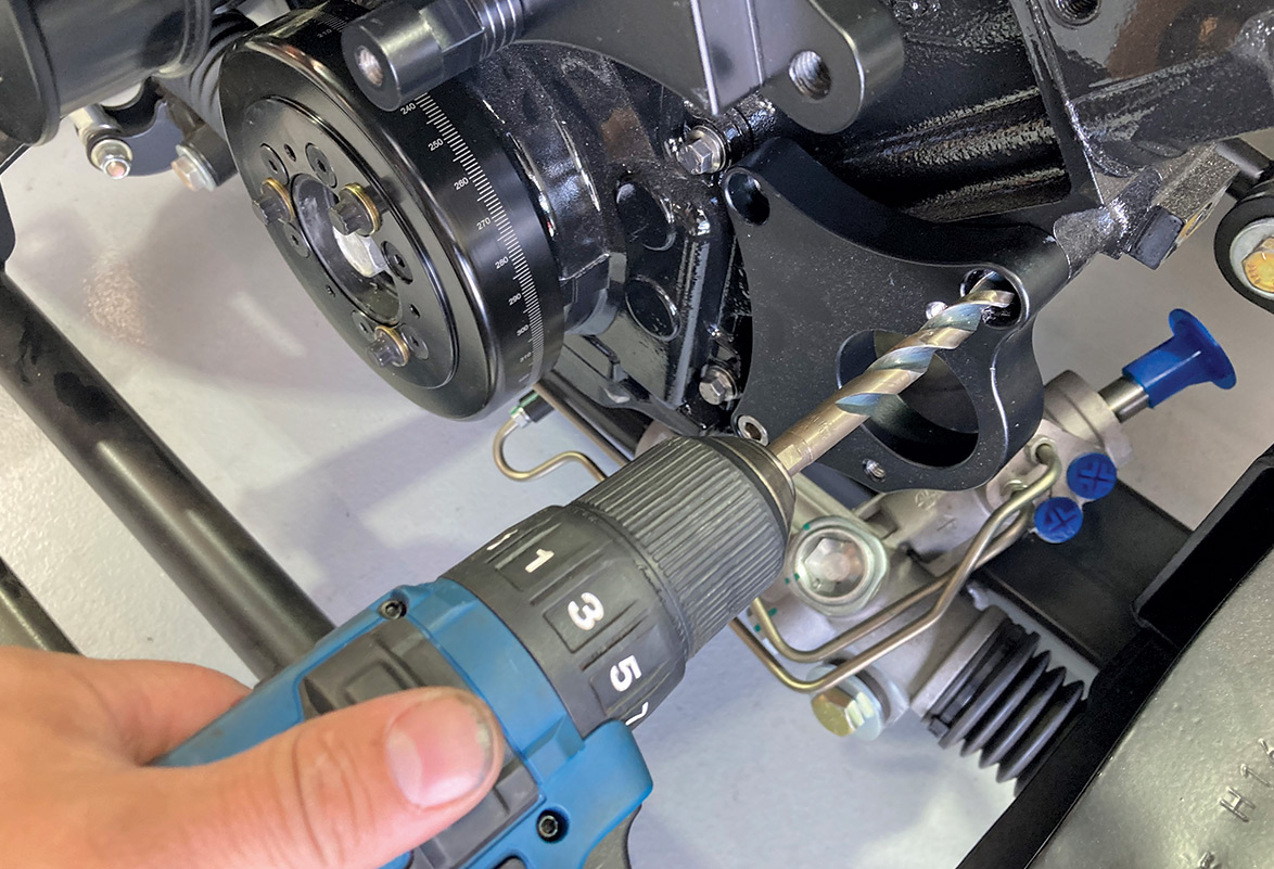
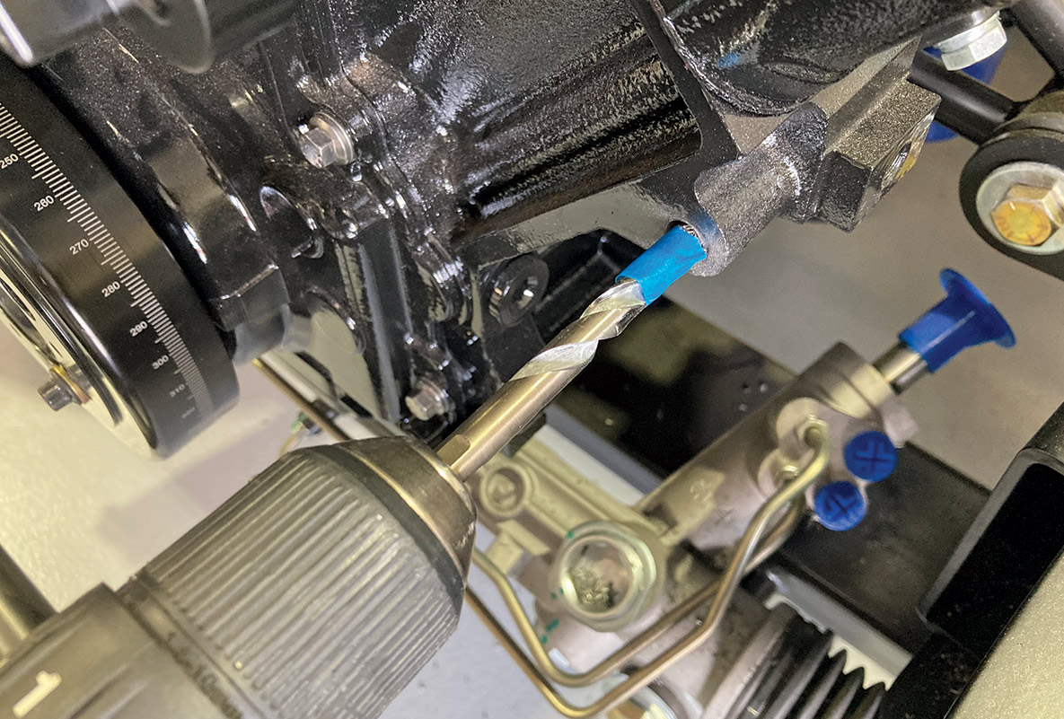
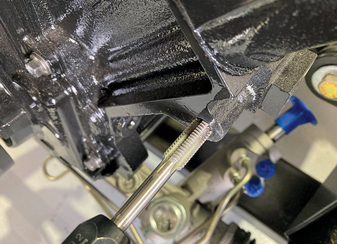
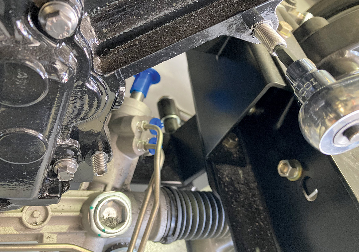
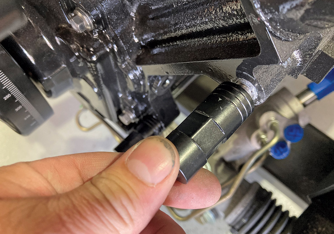
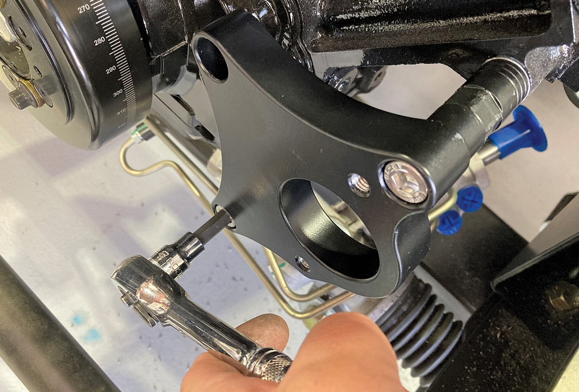
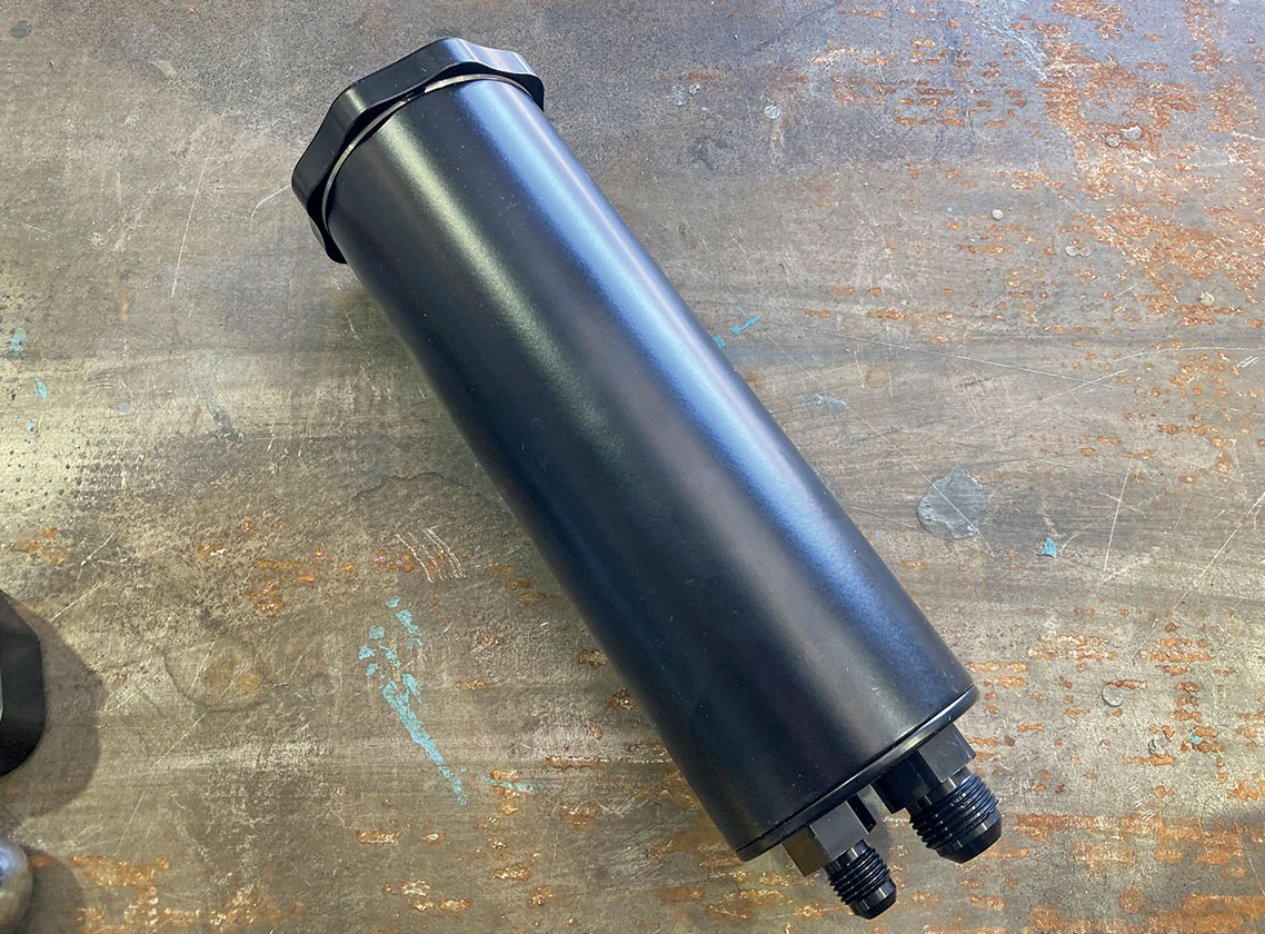
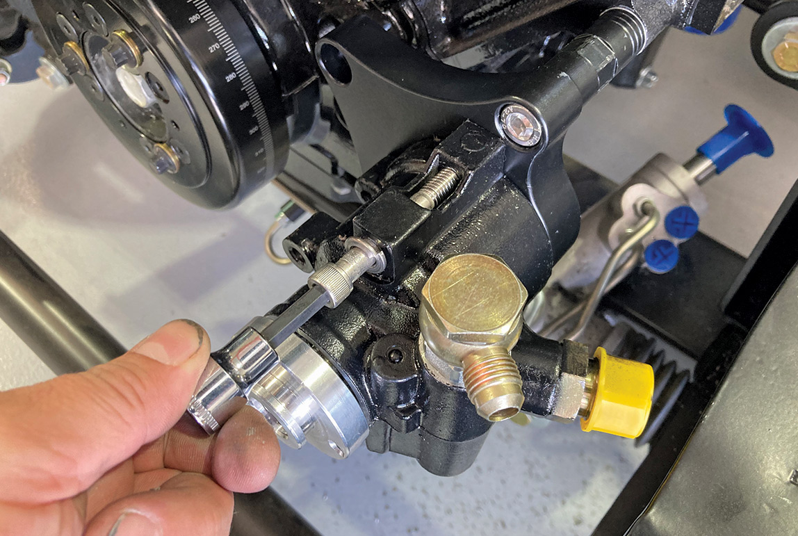
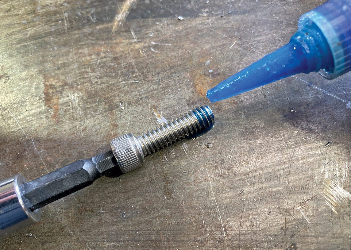
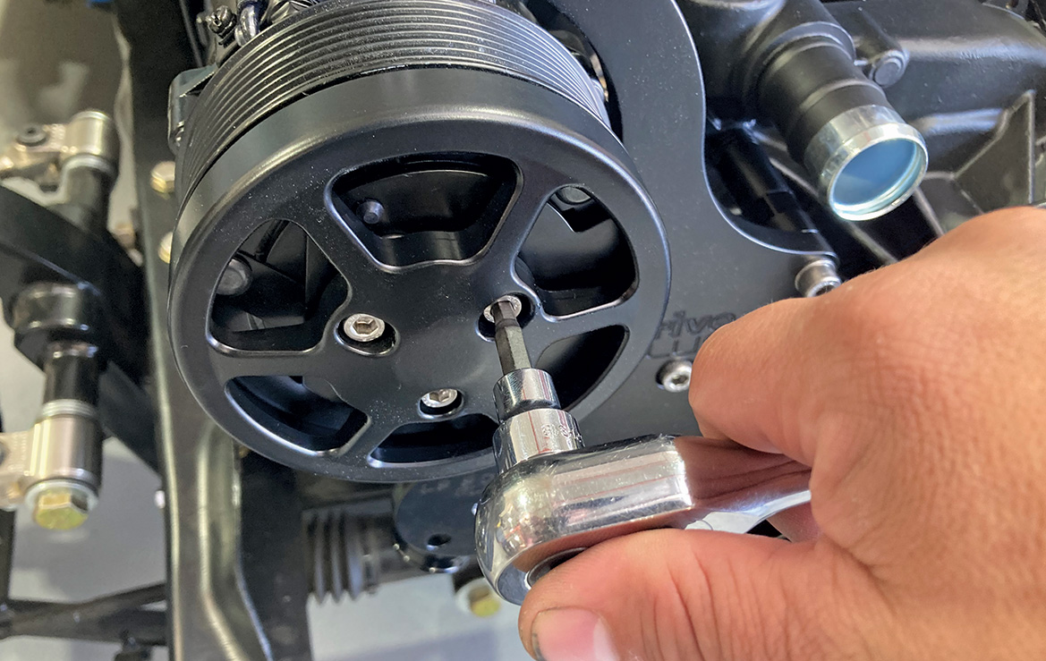
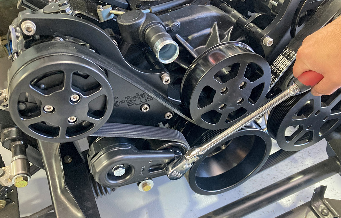
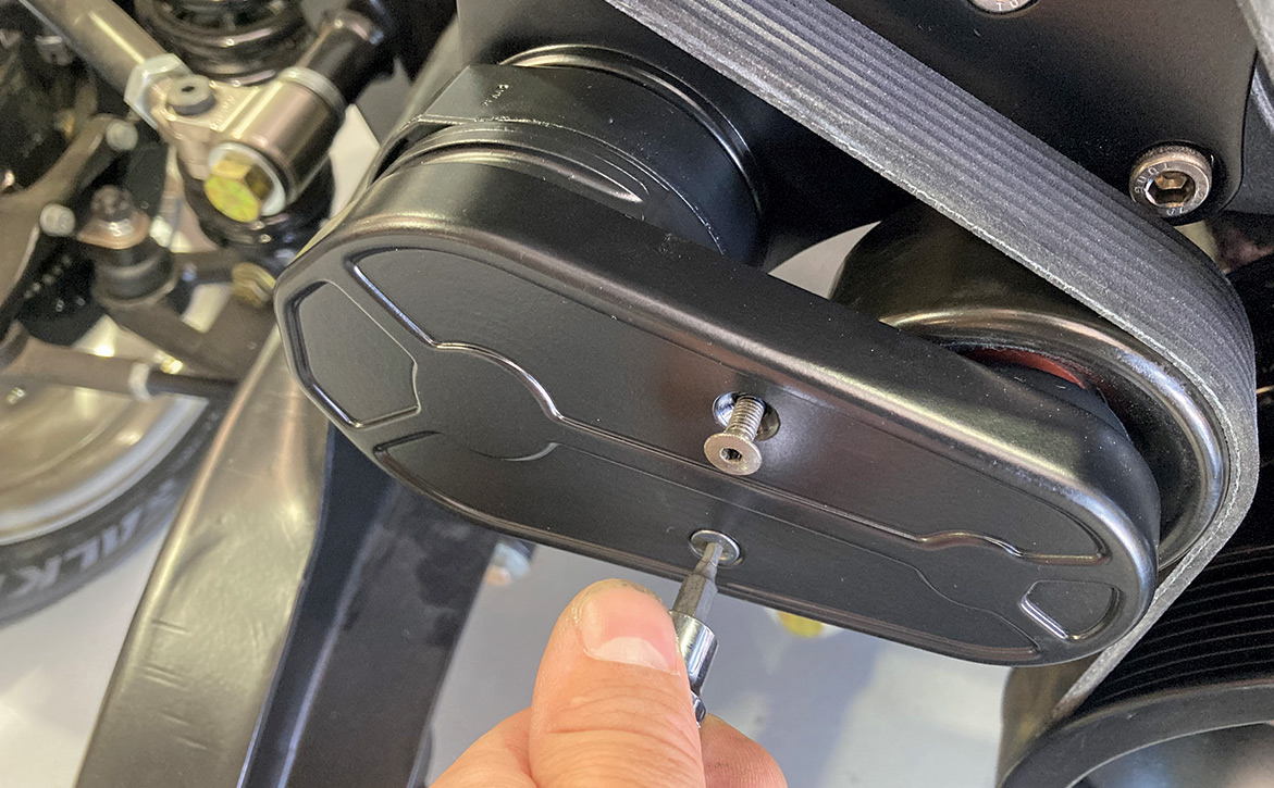
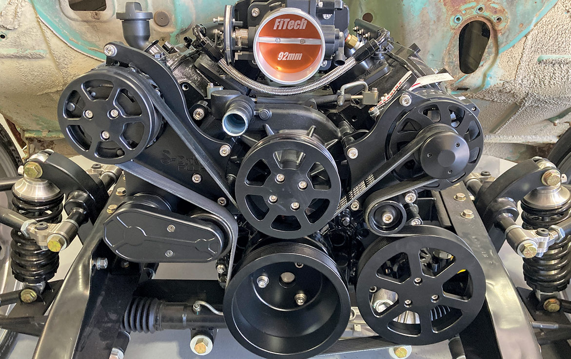
When it came time to choose a pulley setup for the LS engine in our project ’64 C10 it should come as no surprise that we opted for an EMS S-Drive kit. Their reputation for reliability combined with the ease of installation made the decision an easy one. With a clear afternoon, we cleaned off a work bench at the In The Garage Media Tech Center and unwrapped and installed our EMS S-Drive Plus Serpentine Kit on our iron-block LS engine. We think the resulting black-on-black engine package will look great in the C10 and will provide years of reliable motorvation as well!

iron-block LS engine
1. Here’s our iron-block LS engine, just after having received a little TLC and a couple coats of engine enamel and just before it was placed between the framerails of our ’64 Chevy C10.
Eddie Motorsports’ (EMS) S-Drive Plus eight-rib serpentine pulley kit pieces lying on the ground
2. To drive our accessories, we opted to go with Eddie Motorsports’ (EMS) S-Drive Plus eight-rib serpentine pulley kit. This kit comes with everything necessary to equip our LS engine with the capability to provide air conditioning and power steering to our C10, as well as a high-amp alternator, all in a single package. The high-performance eight-rib belt kit can handle 33 percent more torque and horsepower than standard six-rib kits, while the CNC-machined billet aluminum brackets and pulleys provide a precision that is unmatched. Finished in Fusioncoat Raven Black, EMS also offers all its S-Drive kits in polished, anodized, natural, and a variety of other Fusioncoated versions as well.
Close up of a cleanup tap checking the holes on the engine block
3. Before we get started on the installation, every hole in the front of the block and heads was chased using a cleanup tap to ensure all the threads are free and clear of any detritus.
Close up of a SFI-approved crank damper being installed
4. The first item up for installation is this provided SFI-approved crank damper. Note the use of the proper installation tool to ensure the damper is fully seated and that the threads of the crank remain undamaged.
Close up of an OE GM crankshaft bolt being installed
5. Next, an OE GM crankshaft bolt is installed and torqued to OE specs. These bolts are of the torque-to-yield variety and are a “one and done” deal. Once installed and torqued to spec, they need to be replaced rather than reused.
close up of stainless studs that provide a mounting point for additional brackets and a measuring tape at 3 inches
6. A handful of stainless studs are used to retain the water pump and provide a mounting point for additional brackets; three on the passenger side and two on the driver side. The passenger side studs measure 92mm and should be installed to a length of 3 inches from the surface of the block …
close up of stainless studs that provide a mounting point for additional brackets and a measuring tape at 4 inches
7. … while the driver side pair are slightly longer, measuring 118 mm with a stickout measurement of 4 inches.
A water pump gasket being installed
8. With the studs in place, a pair of water pump gaskets are installed, with a thin coat of RTV sealant applied to both sides before the provided water pump is slid into place.
rear alternator bracket<br />
placed over the driver side studs and secured with a socket capscrew
9. Next, the rear alternator bracket is placed over the driver side studs and secured with an M8x90mm socket capscrew.
A pair of stand-offs being installed
10. A pair of 3/4×1.41-inch stand-offs are then installed hand tight onto the two studs, using antiseize to prevent galling of the stainless components. Note the hex portion of the standoff is facing away from the engine.
three standoffs being installed on the opposite side of the engine
11. On the opposite side of the engine, three 3/4×2.55-inch standoffs are installed in a similar fashion on the corresponding studs.
fully indexable thermostat housing being installed
12. The fully indexable thermostat housing is installed next, with the air bleed of the thermostat itself facing up to prevent overheating due to air pockets in the system.
A pair of capscrews being used to attach the rear A/C compressor bracket
13. A pair of M10x20mm capscrews are used to attach the rear A/C compressor bracket to the passenger side of the water pump.
A dab of blue threadlocker on a capscrew
capscrew affixing the water pump pulley
14-15. A dab of blue threadlocker is applied to the four 5/16-24×1-inch capscrews that affix the water pump pulley to the water pump to ensure it remains in place.
Hand pointing to mounting holes on block
16. Some LS blocks only feature a single mounting hole on the lower driver side section of the block, requiring a second hole to be drilled and tapped into it. First, the power steering bracket is attached using the lower mounting hole and the provided M10-1.5x25mm fastener, carefully aligning the bracket’s top right hole with the center of the boss on the block.
Hand using a drill on the mounting bracket
17. Next, the center of the mounting hole of the bracket is transferred to the block using either a transfer punch or an appropriately sized drill bit.
“Q” drill bit, drilling on mounting block
18. Using a “Q” drill bit, a hole is drilled into the block 11/16-inch deep. Note that we’ve taped our drill bit off to serve as a “depth guide.”
bottoming tap threading the hole after being drilled
19. Once drilled, an M10-1.5mm bottoming tap is used to fully thread the hole.
A pair of setscrews
20. A pair of M10x40mm setscrews are then installed …
stainless standoff being installed
21. … followed by a pair of 3/4×1.745-inch stainless standoffs.
power steering bracket being installed
22. The power steering bracket is then fastened to these standoffs using a pair of M10x20mm capscrews.
a remote-mounted power steering pump reservoir laying on the ground
23. We opted to go with a remote-mounted power steering pump reservoir for our installation and EMS provided this gorgeous powdercoated aluminum reservoir that will be mounted in the engine compartment.
GM Type-II power steering pump being installed with socket head capscrews and lock washers
24. The GM Type-II power steering pump provided with the S-Drive Plus kit has been powdercoated to match the rest of our components and installs on the bracket using a pair of 5/16-18×3-inch socket head capscrews and lock washers.
a dab of threadlocker being applied to a fastener
power steering pump pulley being attached to the pump’s drive hub
25-26. With the power steering pump in place, four 1/4-20×5/8-inch fasteners are given a dab of threadlocker before affixing the power steering pump pulley to the pump’s drive hub.
Powermaster alternator laying on ground
27. To ensure the charging system of our C10 keeps the battery fully topped up, EMS provided a Powermaster alternator spec’d at 104 amps at idle with a total max of 172 amps at the top end. Note the eight-rib pulley and matching fan has already been installed on the powdercoated alternator.
alternator bracket being installed
28. The alternator bracket attaches to the pair of standoffs mounted on the driver side of the water pump using a pair of M8x25mm capscrews and AN washers. The alternator is then installed using one M10x80mm socket screw through the bottom bolthole and one M8x25mm socket screw at the top.
crankshaft pulley being installed
29. A trio of 3/8-16×1-1/4-inch fasteners dipped in threadlocker are used in conjunction with Belleville washers to hold the crankshaft pulley snug against the damper.
A/C bracket being installed
30. Next, the A/C bracket is installed using three M8x25mm capscrews affixed to the water pump standoffs previously installed.
Sanden-style A/C compressor being installed
31. The Sanden-style A/C compressor is installed next, using two M8x25mm capscrews and a special 1/2-inch shoulder bolt at the lower rear mount.
A/C compressor cover installed
32. An A/C compressor cover dresses up the rather ugly front of the compressor and attaches using a pair of 1/4-20×3/4-inch socket capscrews shod in a dab of threadlocker.
hand holding an EMS trick A/C compressor manifold
33. EMS provides this trick A/C compressor manifold that makes routing the A/C hoses a cleaner affair than the standard ports allow, but it shouldn’t be installed until the rest of the A/C system is in place and ready to receive a charge.
hand installing a GM-style tensioner
34. The GM-style tensioner installs on the A/C bracket using a threadlocked 3/8-16×2-1/4-inch hex head bolt.
Installed serpentine belt with hand tightening a bolt
35. Routing the wide, eight-rib serpentine belt is one of the last appointments of an EMS S-Drive Plus Serpentine Kit installation.
installation of the billet aluminum tensioner cover
36. The very last task is the installation of the billet aluminum tensioner cover, fastened by a pair of 10-32×3/4-inch hex drive flathead screws.
Completed EMS S-Drive Plus kit
37. Our EMS S-Drive Plus kit locates all the accessories in a tight manner to the LS engine block, preventing any notching in the frame or fenderwells, while the eight-rib serpentine belt setup and additional idler pulley between the alternator and power steering pulley ensures that each accessory gets the proper belt tension required to keep things spinning without slipping. The black Fusioncoat finish also looks great and complements the all-black aesthetic previously applied to the LS engine.
In The Garage Media, Tech Center graphic
 SOURCE
Eddie Motorsports
(888) 813-1293
eddiemotorsports.com