
 Tech
Tech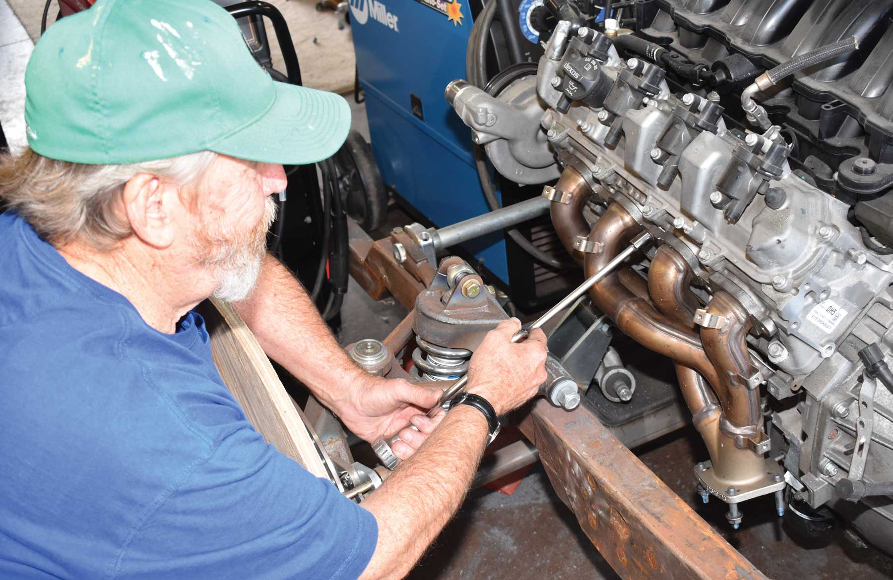

BY Ron Ceridono Photography BY The Author
y now everyone knows how popular the General Motors LS family of engines have become for performance applications. Their potential for producing reliable, affordable horsepower is unmatched. But oddly enough, when these engines first came on the scene, some critics complained that GM was still using “old school” two-valve heads with a single cam in the block and pushrod valvetrains. Many armchair engineers opined that technology dictated combustion chambers with lots of valves operated by multiple overhead cams were necessary for a modern performance engine. Suffice it to say they were wrong and GM was right.
While the LS series of engines did stick with a conventional valvetrain layout there was good reason for it. It makes for a much more compact V-8 than an overhead camshaft arrangement (as even fans of the Ford Coyote will have to agree). But just because the LS series has pushrods doesn’t meant it’s not loaded with modern technology. The deep-skirted LS block with cross-bolted main bearing caps makes for a stout lower end, the pistons are hypereutectic with thin “metric” rings for reduced friction, the camshaft has been raised compared to its small-block predecessors to allow for not only a larger-diameter cam and bearings but a larger-diameter crankshaft as well, and the list goes on. But arguably the real technological advance of these engines can be found in the heads. The 15-degree valve angles allow for superior airflow, the ports are evenly spaced and symmetrical (as opposed to the Gen I and II small-blocks with the center exhaust valves and ports next to each other). The rocker arms are still stud mounted, but this time around the ratio has been increased from 1.46:1 to 1.7:1, a rocker arm cradle has been added, and beehive springs are used. There’s all that and lots more to make the LS loveable, but GM hasn’t been resting on its technological laurels and the next advancement in design is direct fuel injection.
Recently our friend and fellow classic truck aficionado, Paul Willis, decided to build a ’55 Ford F-100 that would be sophisticated enough to replace his ’15 Chevrolet Silverado as an everyday driver. We’ve followed along in CTP as the Ford’s original frame was equipped with a Speedway Motors G-Comp front suspension clip up front and a C4 Corvette IRS in back by way of a Flat Out Engineering installation kit (see CTP July ’21 issue). Obviously the chassis was going to make for a great driver, so when Willis went looking for an equally user-friendly engine for this new project the first thought was an LS. But then for a truly sophisticated, everyday ride he thought, why not go for the latest technology, a Gen V LT direct fuel injection V-8 like the one under the hood of his current pickup.
Rather than deliver fuel to the intake tract outside the intake valve, as is done with like throttle body and multi-port systems, direct injection introduces fuel into the cylinder. The advantages of this are many, such as increased fuel economy, better power, and lower emissions. Of course to inject fuel directly into the cylinders requires a high-pressure delivery system, consequently these engines have a unique pump at the back of the block that is under the intake manifold and driven by the camshaft. Pressure from this pump can exceed 2,000 psi, which is necessary to overcome the pressure in the cylinders on the compression stroke. To find out more about the Gen V direct-injected engines, check out Ryan Manson’s excellent article, “Everything You Want To Know About The GM Gen V LT1 Engine” in the June ’22 issue of CTP. For our purposes here we’re concentrating on the differences between an LS and a Gen V engine in terms of installation in a classic truck.
Some of the most obvious differences in the Gen V and earlier engines are the location of the water pump and as a result the configuration of the front drive system. There’s no power steering pump thanks to the electric power steering that GM is now using. Some of the more subtle differences between the Gen V engines and the earlier LS engines are the location and spacing of the engine mount bosses on the block, the oil pans are different and won’t interchange nor will the exhaust manifolds due to the Gen V’s unique bolt spacing, and the bellhousing bolt patterns are different. The top transmission attachment point has been rotated to the passenger side of the block due to the location of the high-pressure fuel pump at the back of the block above the camshaft. Something that will look familiar is the thermostat housing in the engine’s upper radiator hose outlet (even though the thermostat housing is plastic).
The contemporary Chevy engine that will take place under this Ford’s vintage hood is an L83, all-aluminum, direct-injected 5.3L (325 ci) from a ’15 Chevy Tahoe. This engine has 11.0:1 compression and is rated at 355 hp at 5,600 rpm with torque of 383 lb-ft at 4,100 rpm. While there are combinations that will produce more horsepower, this truck is being built as an everyday driver so the engine will remain stock. Backing up the V-8 is a 6L80E transmission with a double overdrive, a gear ratio spread of 4.03, 2.36, 1.53, 1.15, 0.85, and 0.67, and a lockup torque converter.
While the engine and transmission going in this truck are state of the art, we opted for an old-school approach to provide a transmission mount and add some torsional rigidity to the frame by installing an X-member similar to those found under early Fords. We used a universal Super X crossmember kit from Dagel’s Street Rods (dagels.com; 541-378-4434) that included a center crossmember and four X-member legs (kits are also available with two if used as a K-member). The individual components are made from 11-gauge steel that measure 5 3/4 inches deep with 1 3/4-inch flanges. To support the transmission we fabricated a mount from 1/4×2-inch steel strap and bolted it to the bottom legs of the X-member.
When doing any engine swap there are a number of things to consider to prevent problems later on—chief among them are providing sufficient room for a radiator and fan along with the clearance next to the exhaust to route a steering shaft from the column to the steering gear, wherever those components may be. In this case room for the cooling components wasn’t a problem as the engine is set back in the chassis to fit behind the Speedway Motors antiroll bar and move a little weight onto the rear wheels. However, the stock Tahoe exhaust manifolds were bulky enough to make routing the steering shaft difficult. The answer to that problem came in the form of a set of factory headers off a ’20 Camaro with a 6.2L engine.
With the engine and transmission in place there are a few things left to sort out, such as mounting a pump for the power rack-and-pinion and a compressor for the A/C system. Of course making all the electronics required to make the engine and transmission function will be a story in itself. But all that is for another time, so stick around, there’s lots more to come.
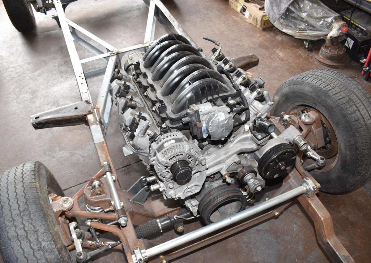
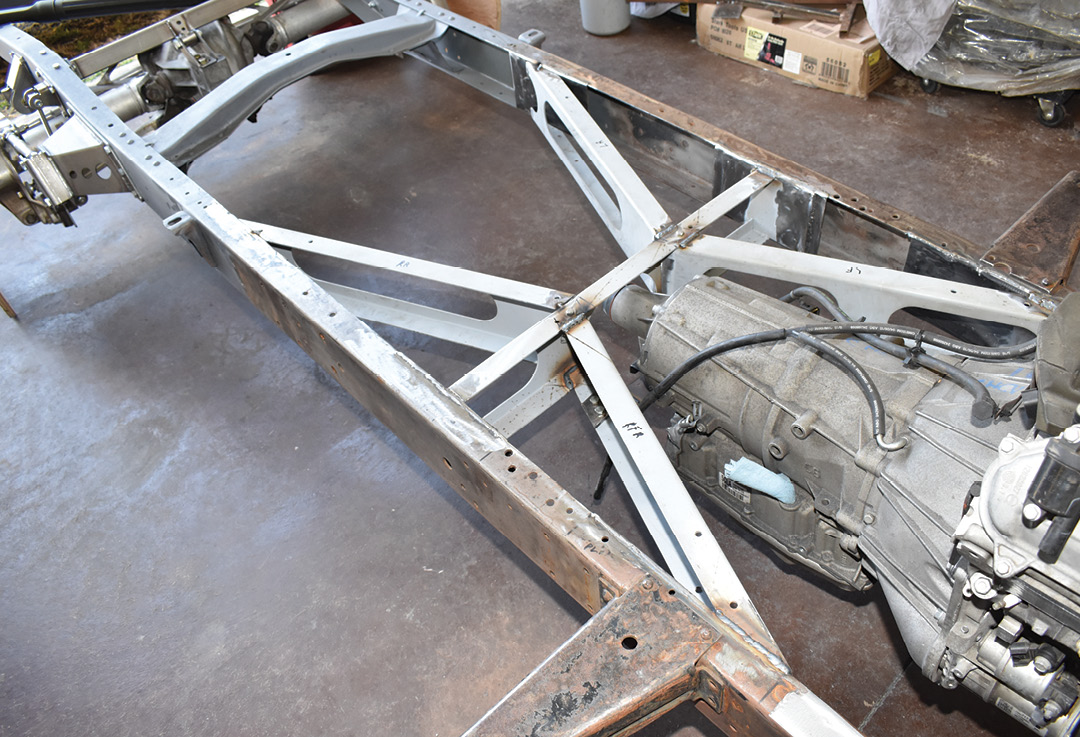
2. The ’55 Ford pickup frame has been equipped with a Speedway Motors G-Comp universal front suspension clip; power will come from a Chevrolet 5.3 direct-injected Gen V engine backed by a 6L80 automatic transmission. Note the position of the L83 water pump (arrow).
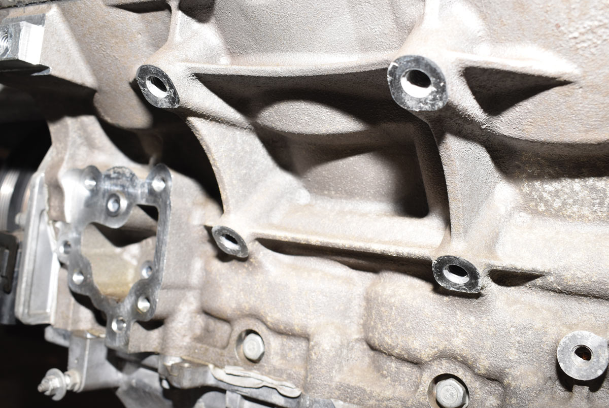
3. One of the many differences between the previous LS series engines and the Gen V is the engine mount pattern on the side of the block—the earlier mounts will not fit.
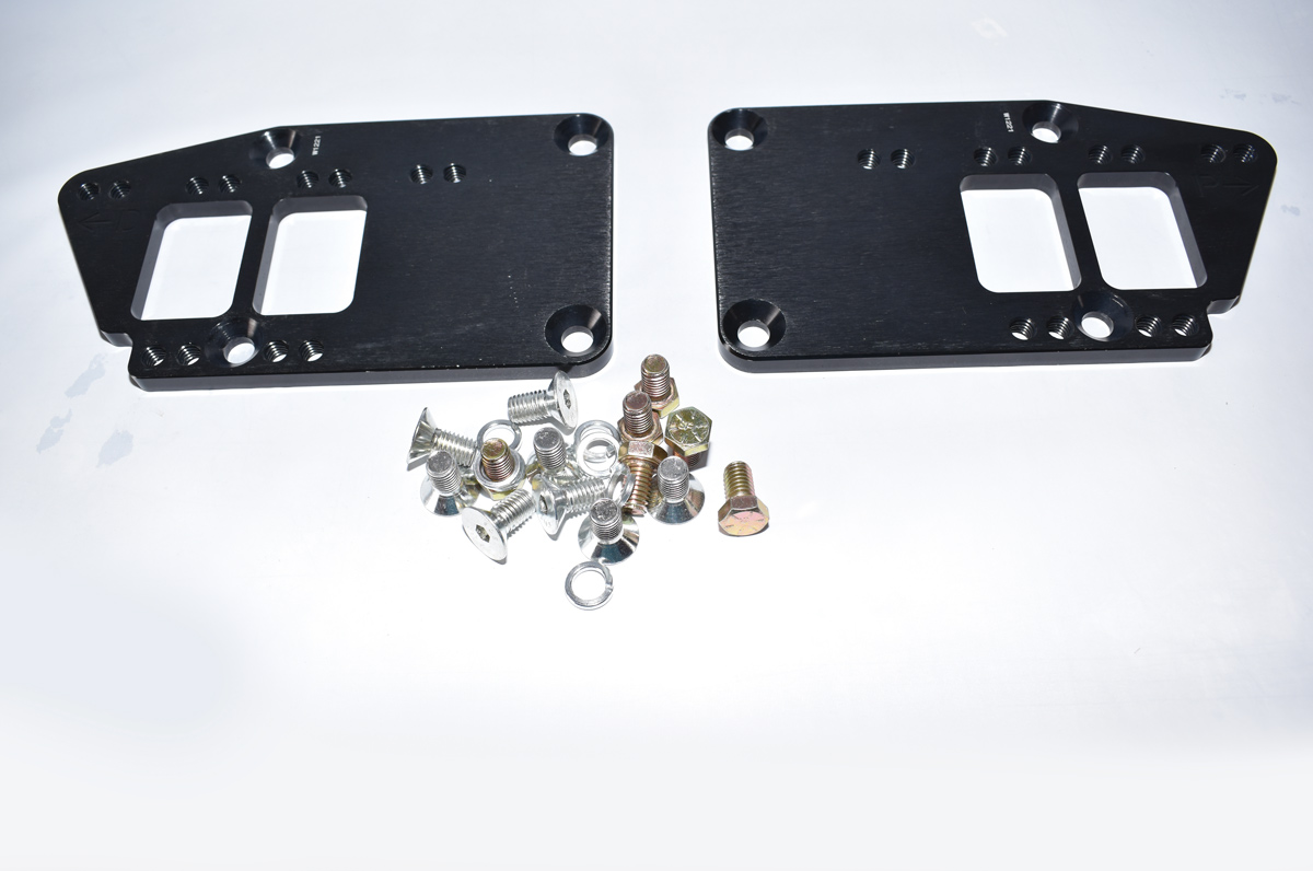
4. Speedway Motors offers these aluminum LT to Chevy small-block engine mount adapters (PN 289-81104BK). They attach to the block with countersunk screws and offer multiple positions to install the engine mounts.
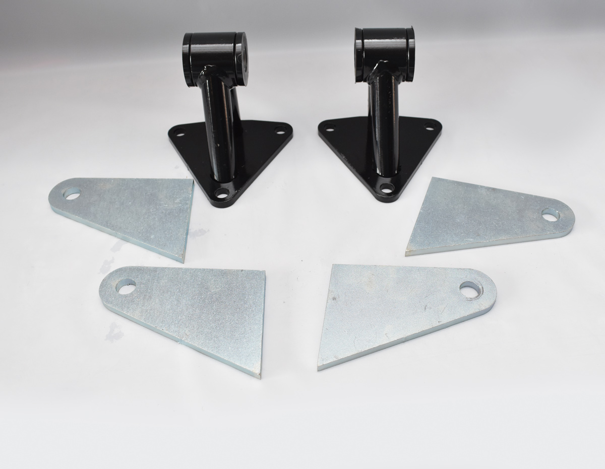
5. The Speedway adapters can accept early style three-bolt engine mounts. We opted for their universal engine mounts with urethane bushings (PN 910-18040) that bolt to the adapters. Frame tabs that may be modified to fit are included.

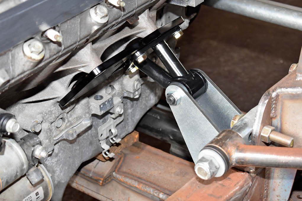
6. With the frame supported on jackstands at ride height and leveled side to side, the engine was set between the rails (it was also leveled side to side). Note the top hole in the transmission (partially hidden by a rubber insulator) has been relocated on the Gen V block (arrow).

7. To center the engine and transmission in the frame, measurements were taken at the crankshaft pulley and the transmission tailhousing. To align with the pinion angle the transmission’s output shaft was pointed down 2 degrees.
8. The engine mount assemblies were installed, all the measurements and angles were double checked, then the frame brackets were welded in place.
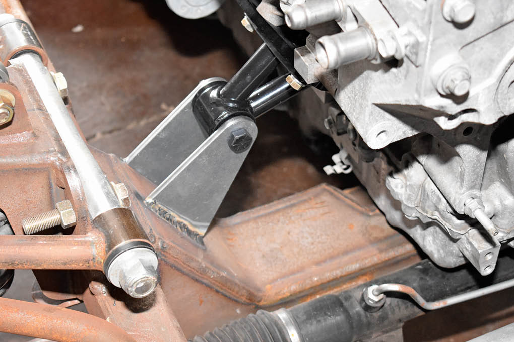
9. Although the Speedway engine brackets are a universal design, as luck would have it they fit perfectly without trimming.
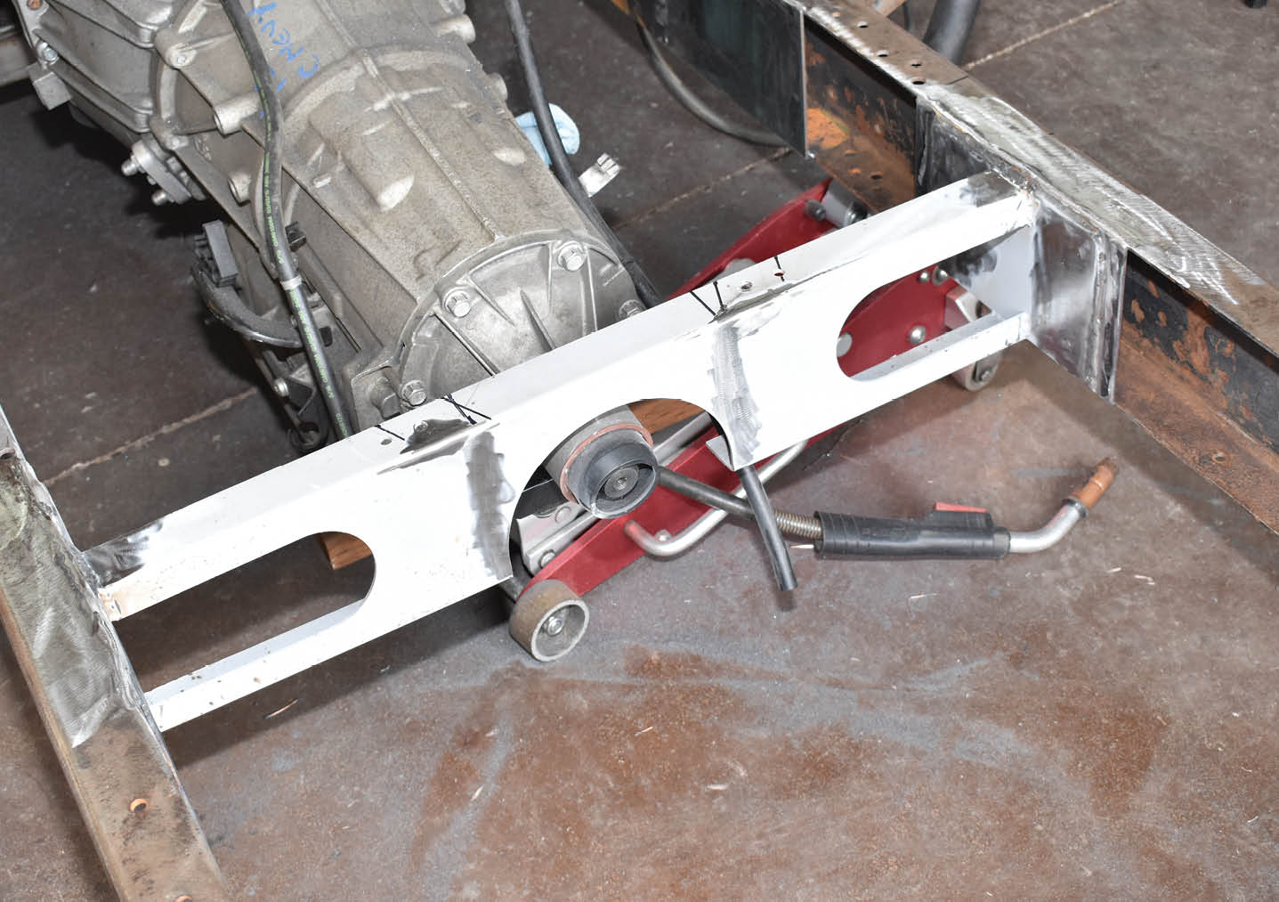
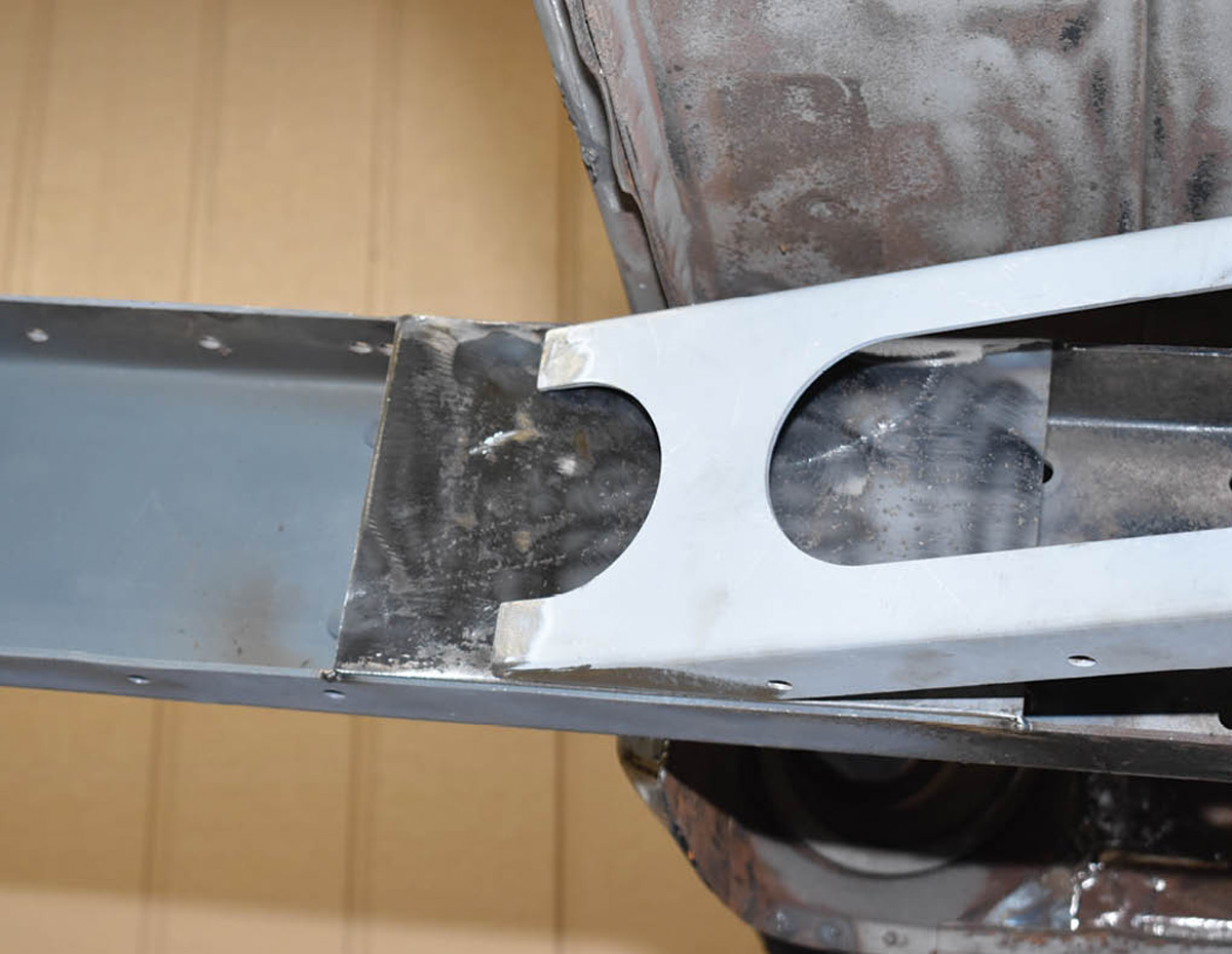
10. The center of the X-member was mounted via boxing plates added to the Ford framerails. The centersection was positioned as far forward in relationship to the transmission as possible.
12. To anchor the X-member legs to the frame four more short boxing plates were added to the framerails. The fuel and brake lines will be routed behind all of them.
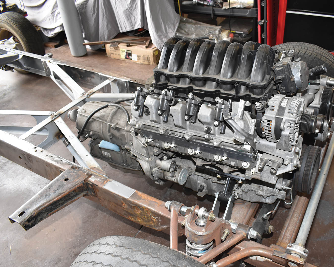
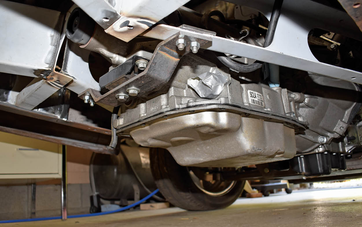
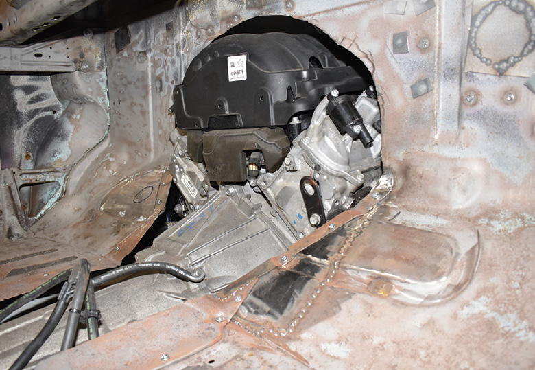
13. Here’s the Gen V engine and 6L80 in their new home. The engine sits behind the G-Force antiroll bar and is positioned as close to the rack-and-pinion steering and the front crossmember as practical.
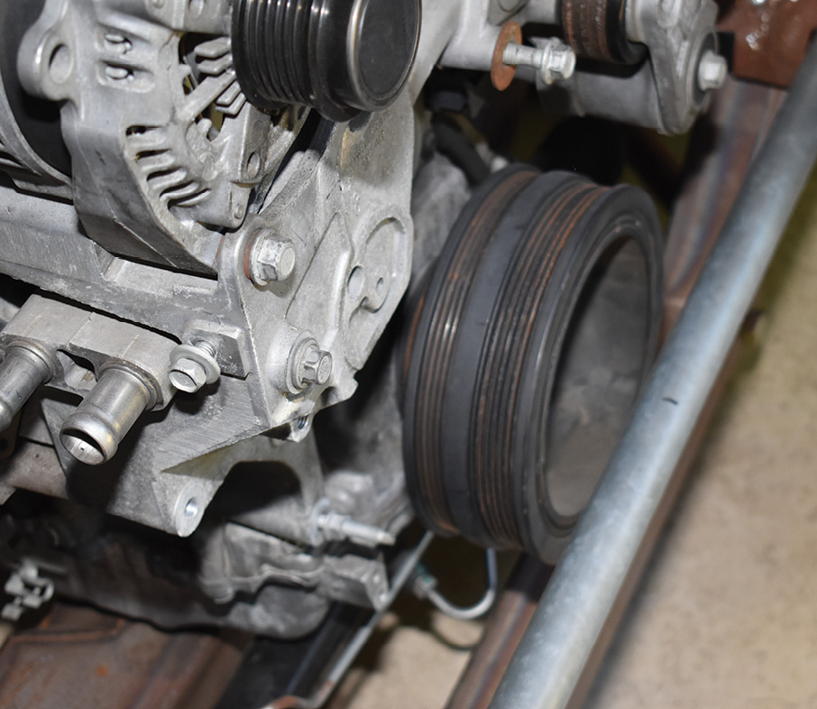
14. While it looks close in this photo, there’s more than enough room between the pulley and antiroll bar to change the serpentine belt, if necessary. To remove the pulley/damper assembly the bar is easily removed.
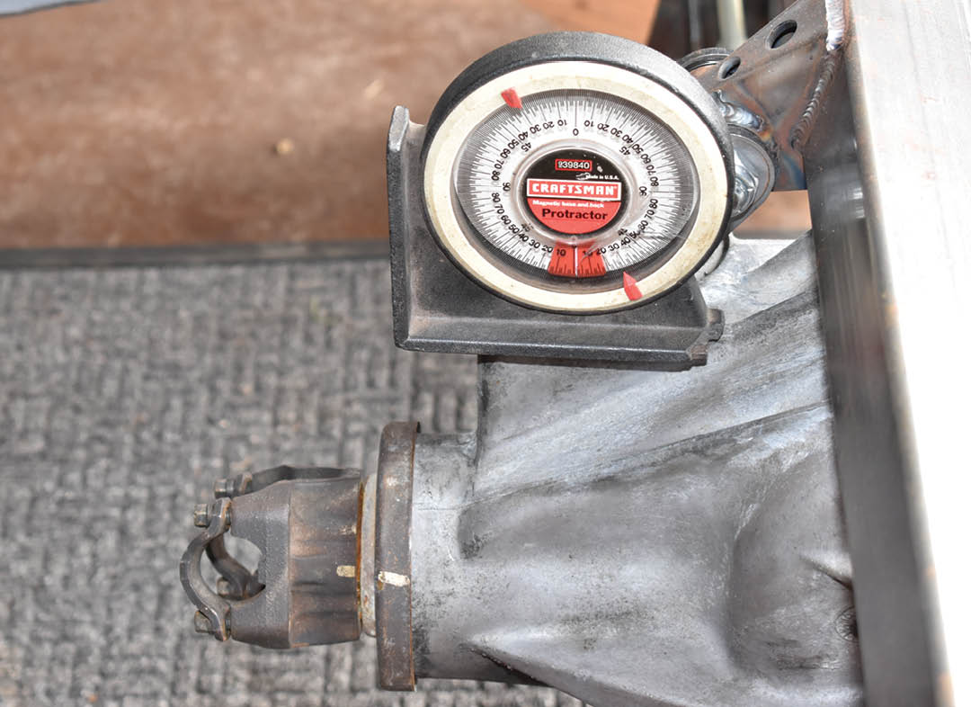
15. At ride height the pinion is pointed up 2 degrees to match the transmission. As the Corvette centersection is solidly mounted, the U-joint operating angles will remain constant, eliminating a possible source of vibration.
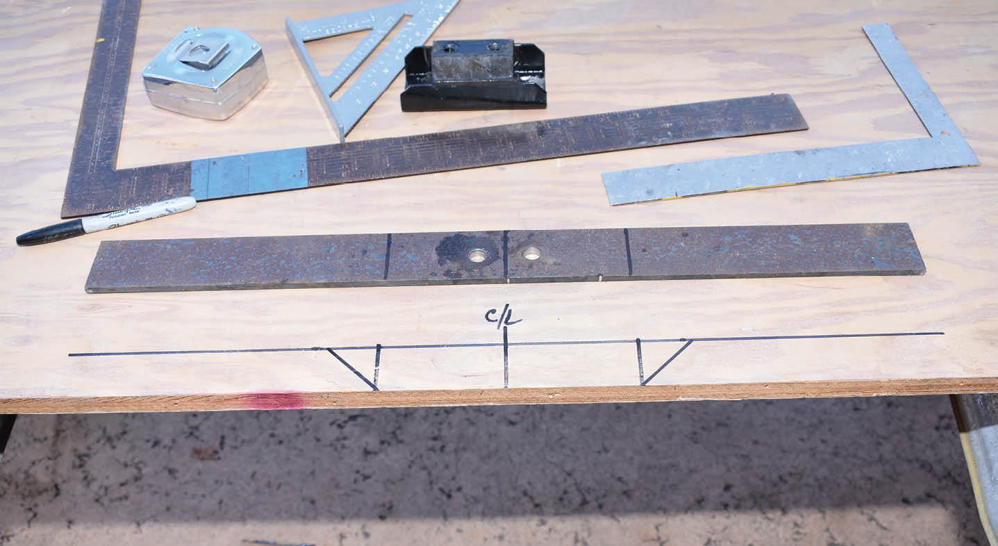
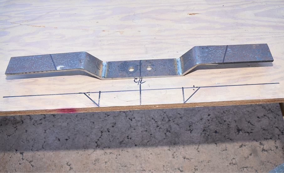
16. To fabricate a transmission mount we drew the necessary shape on a scrap piece of plywood to act as a template. The center of the crossmember was determined and the holes for the transmission mount were drilled in the flat stock.
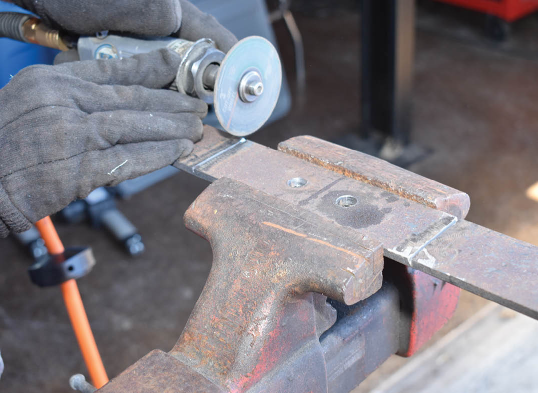
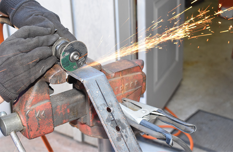
17. Forming the 1/4×2-inch flat stock was done by using an abrasive wheel to cut slots roughly a quarter way through where the bends would be made.
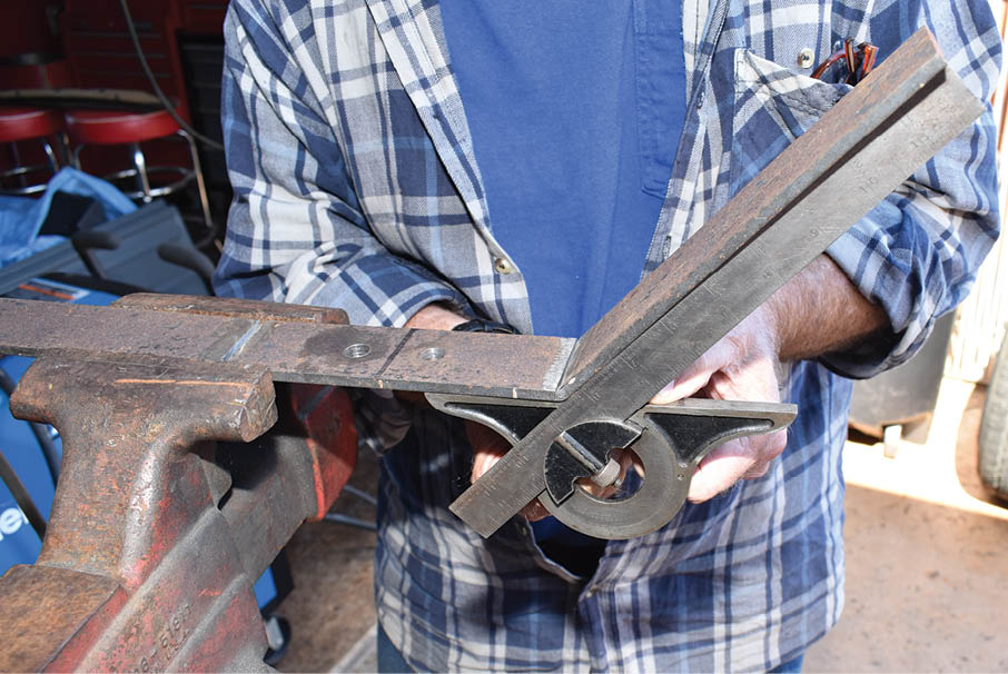
18. With the slots cut, an angle finder was used to make the first bends at 45 degrees. Satisfied with the angle of the bends, the slots were welded.
19. The second set of bends were marked, slotted, bent, and welded like the first.
20. Our simple transmission mount was checked against our template to determine the amount of drop was correct and was found to be spot-on.
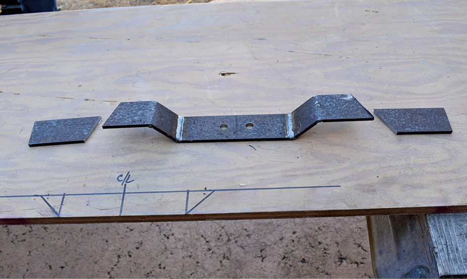
21. All that was left to do was mark and trim the mount to fit the X-member legs.
22. The transmission mount bolts to the bottom flanges of the X-member legs. Short pieces of 1/4-inch flat stock were added to the top of the flanges to act as reinforcements.
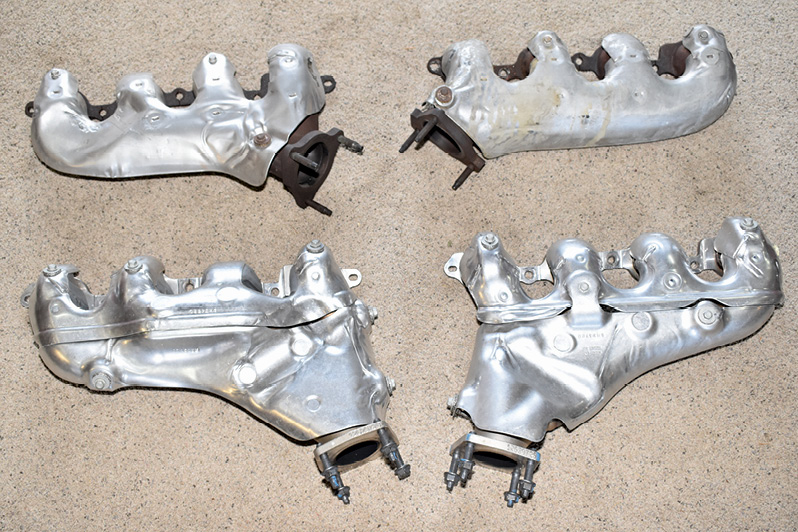
23. Our initial installation of the engine revealed that the stock Tahoe exhaust manifolds (top) made hooking up the steering difficult. We found Camaro factory headers (bottom) solved the problem.
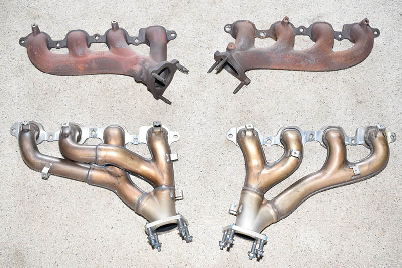
24. Seen without the heat shields, the difference between the Tahoe cast manifolds and the Camaro Tri-Y factory headers is apparent.
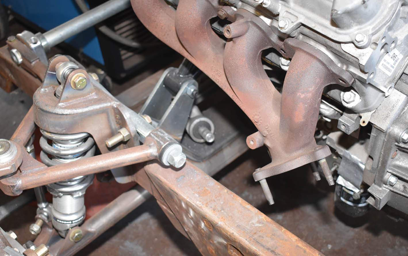
25. While the Tahoe manifolds appear to be well designed for factory cast-iron pieces, the outlet on the driver side would require a number of U-joints to hook up the steering shaft.
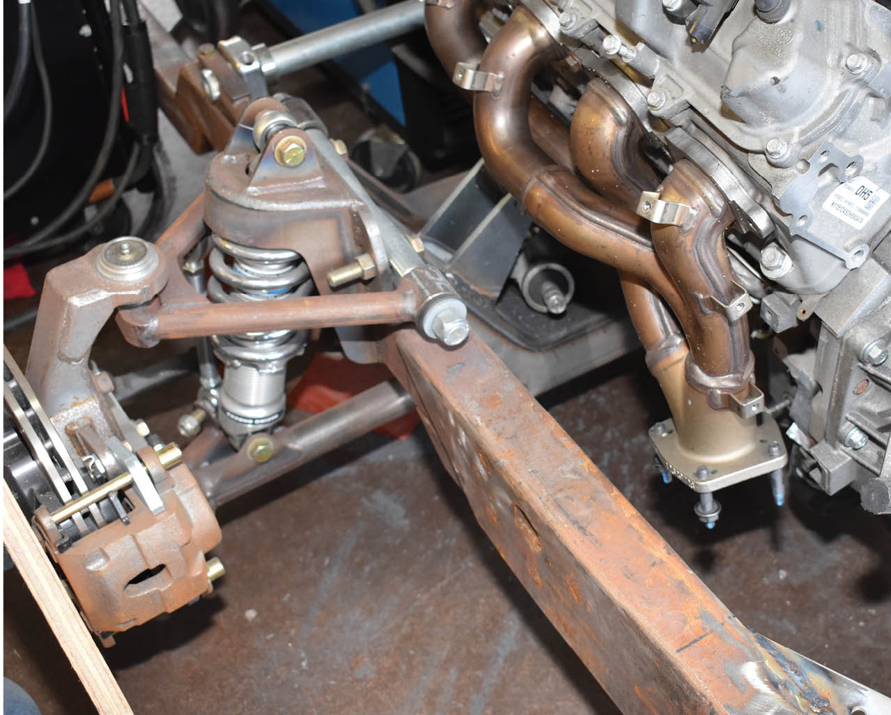
26. By comparison, the Camaro headers tuck in tight and the flanges are lower, providing a much straighter shot and, as a result, fewer U-joints in the steering shaft.
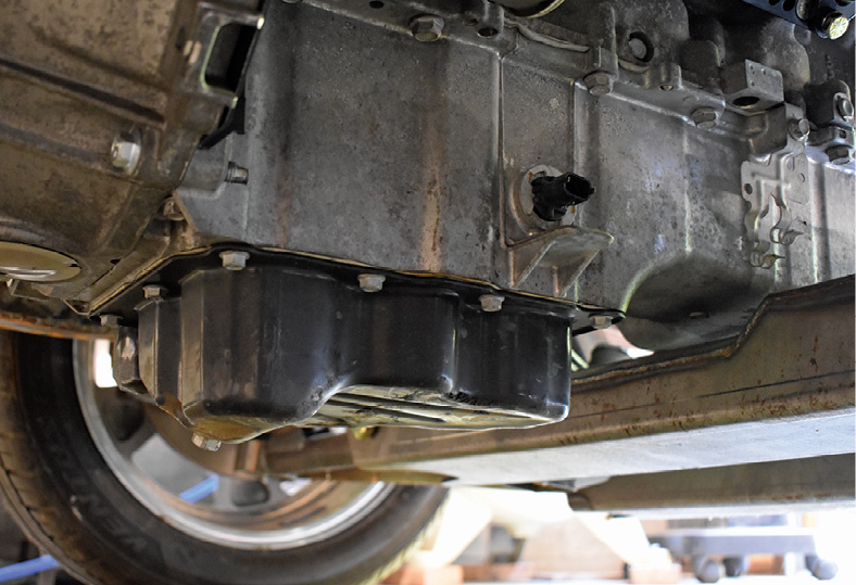
27. A unique feature of Gen V oil pans found on Silverados, Sierras, Tahoes, Yukons, and Escalades is the sheetmetal extension. There are shallower pans available (think Camaro and the aftermarket) but what GM calls the lower sump doesn’t hang below the crossmember, so we’re going to try it.
28. Due to the engine setback, the Ford’s firewall will require some surgery, but it will be worth it to move some weight toward the rear of the truck.
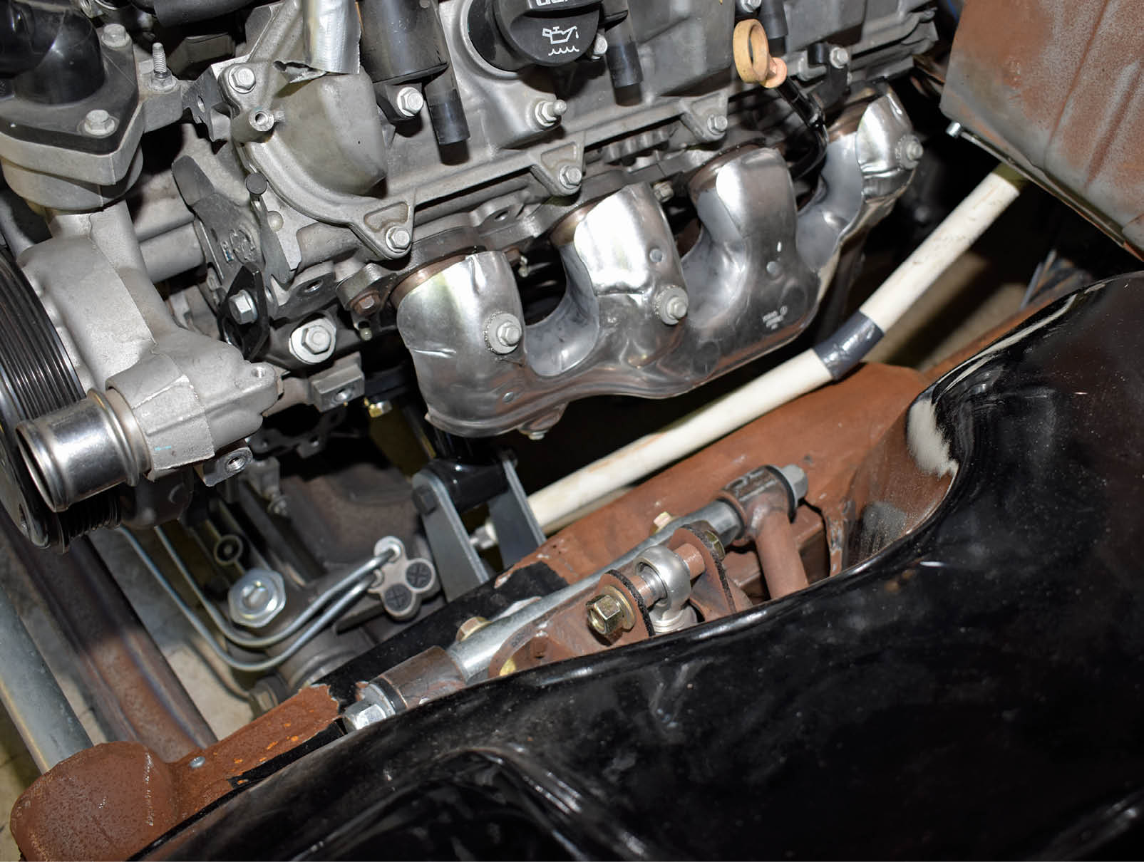
29. With the Camaro exhaust manifolds in place (even with the factory heat shields) we mocked up the steering shaft with PVC pipe and duct tape—only two U-joints will be required.
SOURCE