CTP TECH
InTheGarageMedia.com
American Autowire classic wiring kit instructions being reviewed during harness install
1. After studying the instruction sheets for the American Autowire Classic Update wiring kit, the Howell engine management system, and the Dakota Digital instrument cluster, integrating the three wasn’t as scary as it would appear.
Well Connected
Where Chassis, Engine Management, and Instrument Wiring Meet
By Ron Ceridono Images by THE AUTHOR
A

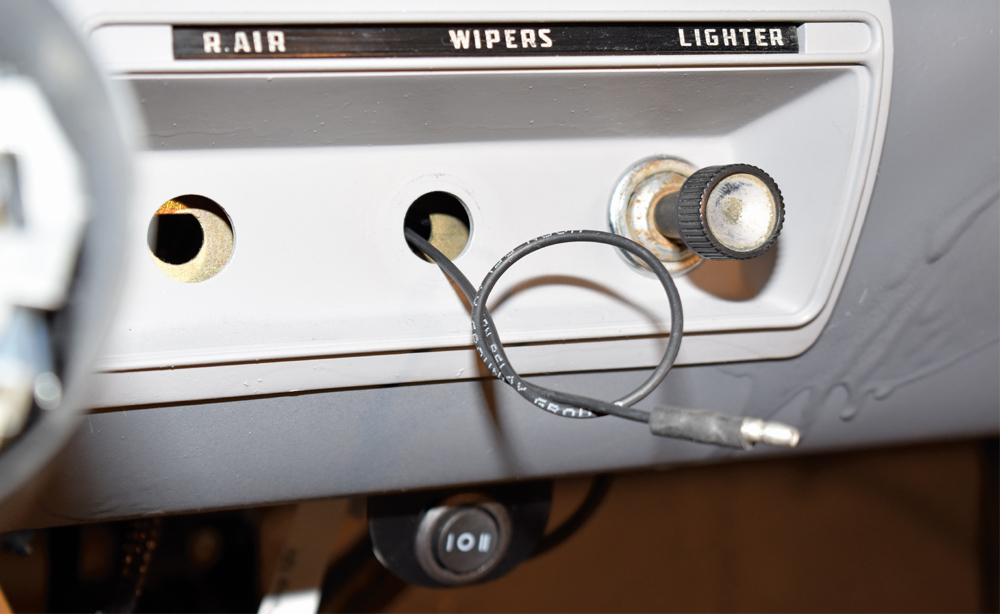
t one time, classic trucks like the 1955 Ford F-100 owned by Paul Willis were basic utilitarian vehicles. This particular example came from the factory with a 239 Y-block V-8 and a three-speed manual transmission. The windshield wipers were vacuum operated and the only option was a heater. But like most of us during the rebuilding process, Paul elected to make some updates to the pickup. He decided to add A/C, power windows, electric wipers, new instrumentation, and a stereo. Of course, all these updates would require updating the electrical system, which is simple enough to do with a new wiring harness like those available from American Autowire.

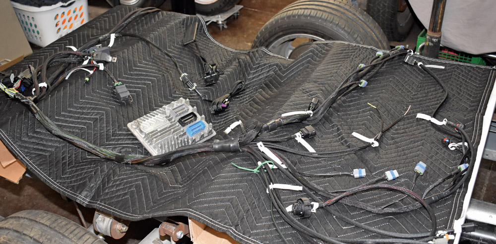
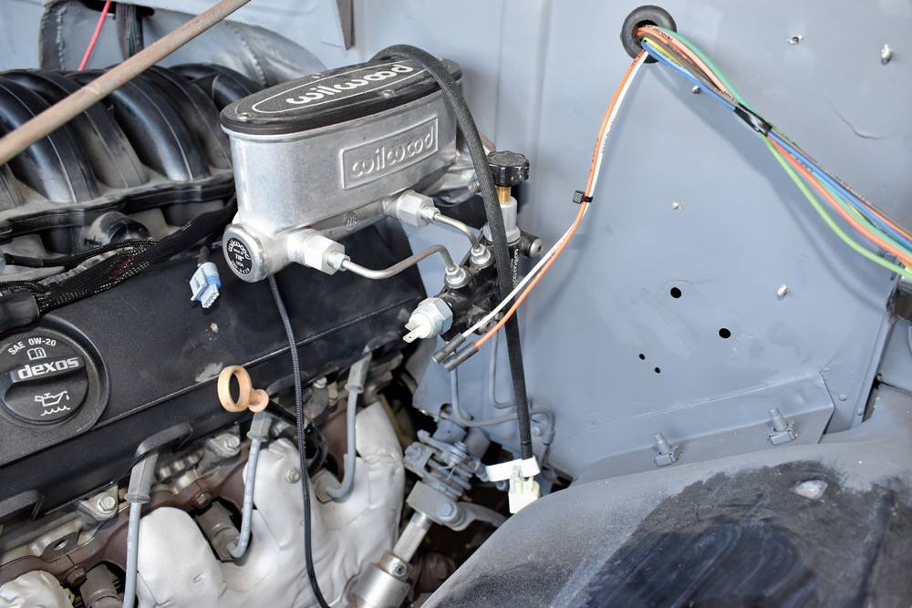
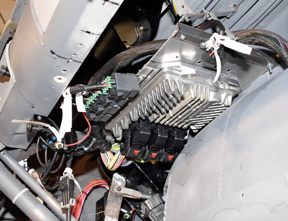
Along with the added convenience items inside the cab, Paul decided to make some changes underhood as well. His powerplant of choice is a Chevrolet Gen V direct-injected L83 V-8 backed by a 6L80 automatic transmission from a 2015 Tahoe. To control the engine and transmission’s functions a wiring harness from Howell Performance was used. This stand-alone system uses modified factory engine and transmission ECMs (electronic control modules) to control their functions and includes a check-engine light, diagnostic connector, and electric fan control.

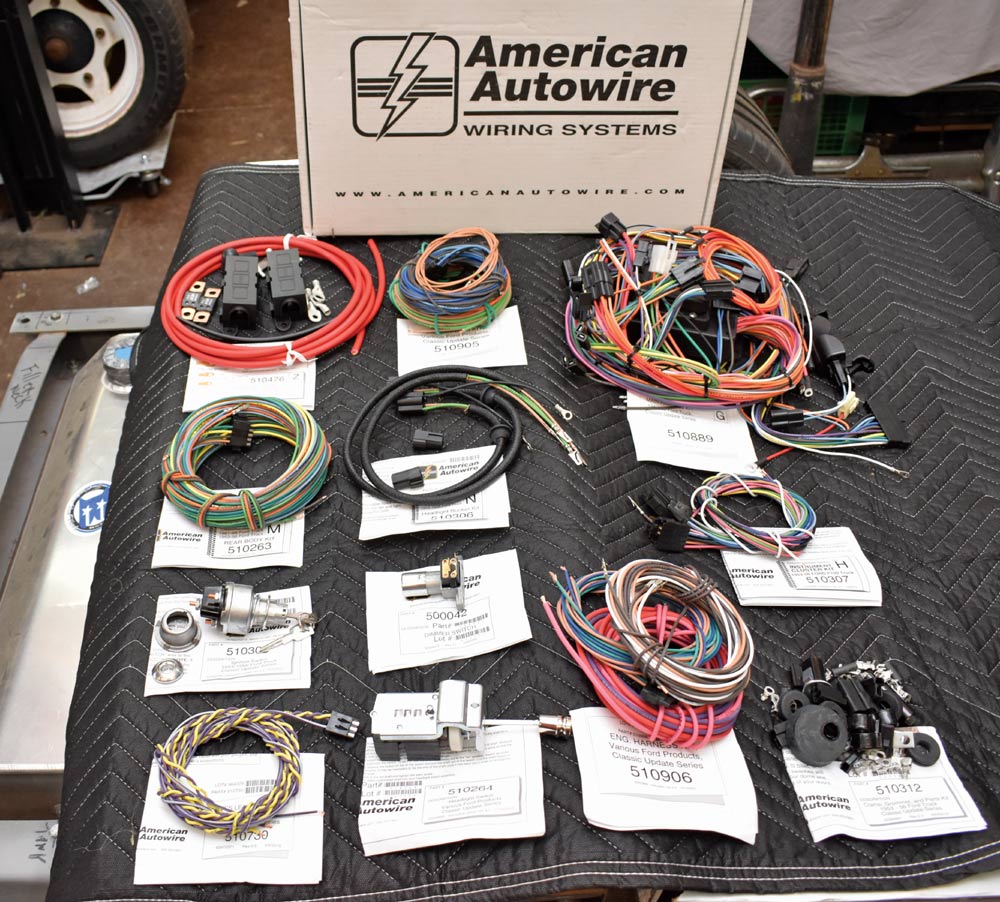
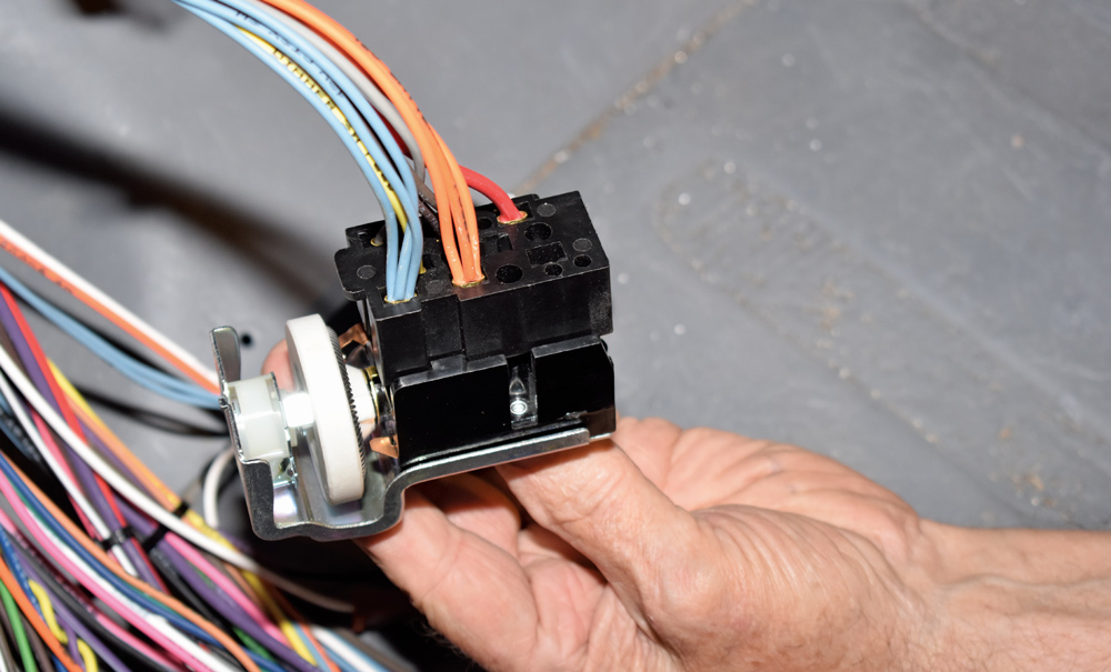
To replace the truck’s dilapidated wiring harness, Paul turned to American Autowire for their Classic Update Kit. These wiring systems are designed for specific vehicles (as opposed to a universal-style kit) and provide more circuits than would have been available in an original chassis or factory-style replacement harness. The Classic Update engine harness provides for updated engine and transmission combinations, while the front light and rear body harness have extra-long leads for custom routing. A 175-amp mega fuse kit with six-gauge charge cable to support a high-output charging system and internally regulated alternator is also supplied. Original-replacement connectors, terminals, and lamp sockets, a headlight switch with 26-amp internal circuit breaker, and new floor dimmer switch are also included, along with a replacement ignition switch compatible with HEI and EFI swaps.

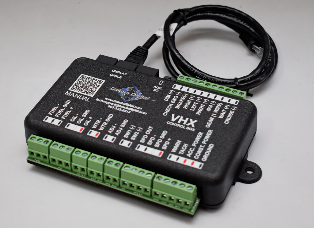
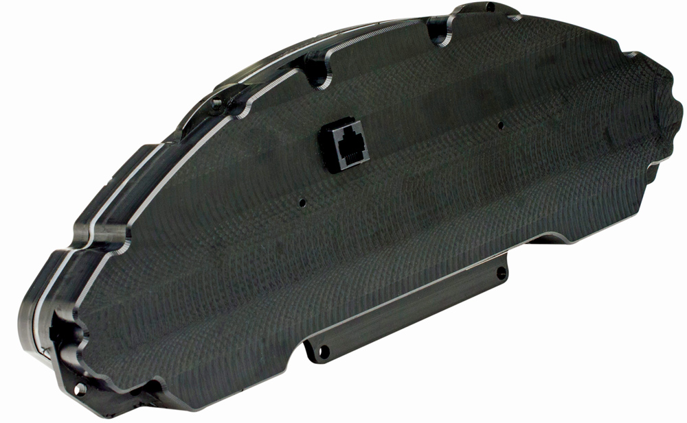
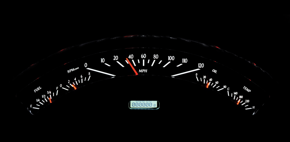
One of the modifications made to the cab of Paul’s hauler was the installation of a 1957 Ford passenger car dashboard that has been updated with a Dakota Digital instrument panel. The VHX System fits directly into the 1957 dashboard without modification. The state-of-the-art panel has analog gauges that include an electronic speedometer, tachometer, oil pressure, water temperature, and fuel level gauges. A digital message center displays the voltmeter, odometer, dual trip meters, clock, and much more (including digital gauge readouts). A unique feature of the VHX instrument panel is the ability to configure the gauges with warning points that appear in the message center. The voltmeter can be configured to flash whenever the voltage drops below the warning value, which can be set from 10 to 13.1 V. The temperature gauge can be set to indicate a high-temperature warning point that will cause a warning message to display; likewise, low oil pressure will cause the message center to flash whenever the value is lower than the warning set point.

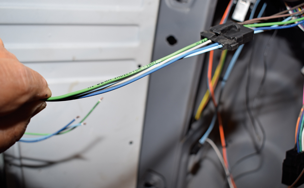
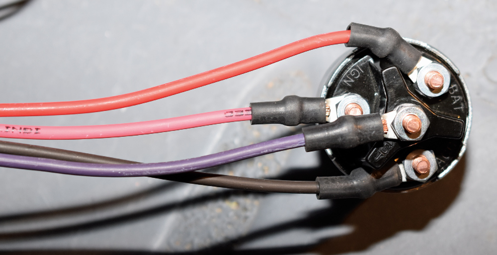
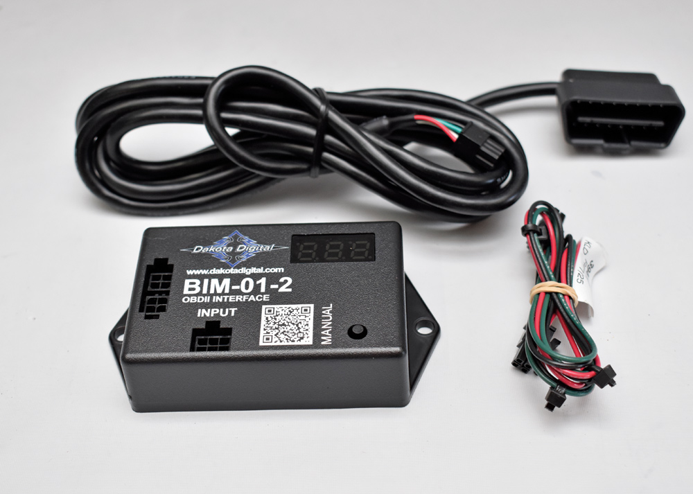
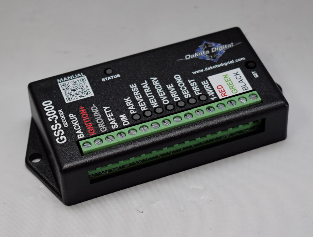
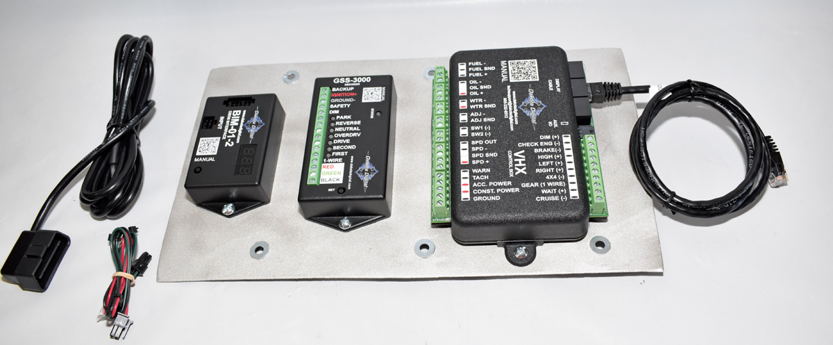
While installing the American Autowire harness, the engine management system and the Dakota Digital instrument panel are all normally straightforward; in this case, the three systems had to be integrated. The wires in the American Autowire harness that normally connect to the starter and ignition switch were connected to the engine’s ECU, which in turn controlled those engine functions. As the ECU also has outputs for engine rpm, temperature, and oil pressure at the OBD II (on-board diagnostics) port from factory sensors, those outputs can be used to operate the Dakota Digital instruments, thereby eliminating the need for additional sender. However, the “signals” the ECU provides cannot be connected directly to the instruments so Dakota Digital offers an “interface” module that converts the ECU’s signals to something the instrument panel can read.

While combining American Autowire with the engine management seems complicated at first, it’s really a simple matter of changing a few connections. In simple terms the ECM controls the engine’s functions—starter, ignition, and fuel injection system—and the American Autowire system will control the ECM. In addition, as the ECM has outputs to supply “information” the Dakota Digital instrument panel requires, no senders are necessary (other than the fuel level sender). The remainder of the electrical items, such as lights and accessories, are connected by the American Autowire harness as they normally would be.

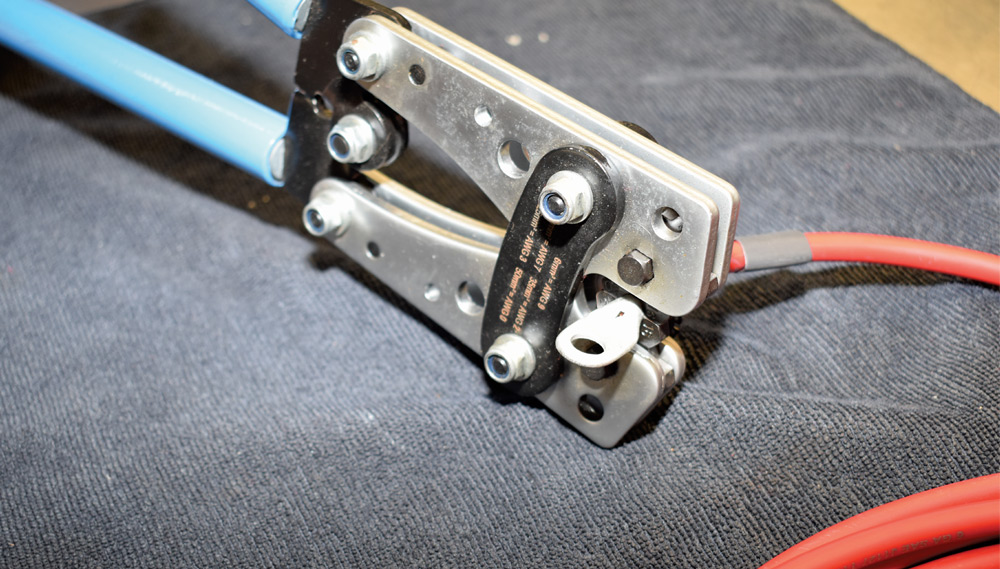
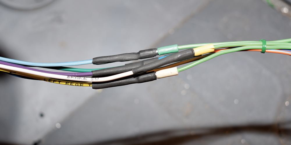
Like any other wiring installation American Autowire suggests that the terminals that may have to be installed are properly crimped (American Autowire has the proper crimping tools available). Note that all crimped terminations already installed are done on a GM-approved 5-ton presses, and soldering these terminations is not necessary. The key to success is to follow the relevant instructions, make sure all ground connections are clean and tight and the wires are protected with grommets where they pass through holes in the sheetmetal and your classic truck will be well connected.

American Autowire harness routing alongside LS engine swap with custom plumbing
2. Under the hood of this 1955 Ford F-100 is a totally stock, Chevrolet direct-injected L83. The 5.3L (325ci) V-8 is rated at 355 hp at 5,600 rpm and 383 lb/ft torque at 4,100 rpm.
American Autowire dash wiring mock-up with classic gauge cluster and switches
3. One of the many sheetmetal mods Paul Willis has made to his truck is swapping the stock dashboard for one from a 1957 Ford passenger car. The instrument cluster is from Dakota Digital.
American Autowire standalone engine harness and ECU layout on workbench
4. This is the American Autowire Classic Update wiring system for 1953-56 Ford trucks (PN 510303). The kit includes wiring with extra-long leads for custom routing, 175-amp mega fuse kit, headlight switch, dimmer switch, and ignition switch.
American Autowire complete wiring kit components organized before installation
5. Installing the engine management system was strictly plug-and-play. All the wires and connections are clearly marked.
American Autowire fuse panel close-up with labeled mini-fuses and cover
6. Included with the Classic Update harness is an ATC fuse panel and fuses, along with modern GXL wire. To simplify installation all wire functions are labeled every 3 to 5 inches.
American Autowire fuse panel mounted inside cab with additional accessory block
7. The new American Autowire fuse panel was mounted to the firewall. Next to it is the fuse panel included with the engine management system.
American Autowire heavy-gauge cable crimped using hydraulic lug crimper
8. Included in the American Autowire kit is a six-gauge charge cable and crimp-on ends to support a high-output charging system.
American Autowire MEGA fuse block wired with high-amp power leads
9. To provide high-amp circuit protection for alternators, batteries, and fuse panels, the wiring kit comes with a 175-amp mega fuse assembly. It comes with fuses, ring terminals, and shrink tubing.
American Autowire headlight switch wiring harness prepared for dashboard install
10. Installing the new light switch is simply a matter of plugging it into the harness. Although this kit is for an F-100, the switch fit the passenger car dashboard.
American Autowire headlight wiring leads identified by color-coding during front harness routing
11. The American dash wire harness connects to the instrument panel. The only wires we used were for dash lights, high beam, and turn indicators. The remaining instruments connect to the ECM.
American Autowire front lighting connector with terminated leads prepared for crimping and installation
12. An adapter is included with the wiring harness to mate with stock or aftermarket steering columns. The six wires with the bullet connectors are from the 1957 Ford passenger car turn signal switch.
American Autowire heat-shrinked wiring splices secured after joining front harness circuits
13. Rather than use the plastic plug we connected the turn signal switch to the wiring harness with original-style bullet connectors. Shrink tubing was used to secure and protect the connections.
American Autowire headlight and turn-signal connectors hanging during front-end harness layout
14. Both a new turn signal flasher and horn relay come with the harness. They were tucked out of sight behind the dashboard.
American Autowire labeled wire bundles staged on fender before routing to engine bay
15. On the left is the bundle of wires for the parking lights and turn signals, middle are the headlight wires, and on the right are the wires for the taillights, stop and turn signals, and gas gauge. There are also optional third brake light and backup light circuits.
American Autowire brake switch wiring routed near Wilwood master cylinder assembly
16. Like Ford did it originally, we’re using a hydraulic brake light switch that is mounted to the Wilwood proportioning valve assembly.
American Autowire ignition switch wiring connected with heat-shrinked power and accessory leads
17. Normally the ignition switch activates the starter and ignition. In this application those terminals connect to the ECM. The power and accessory terminals connect to the American Autowire harness.
American Autowire ECU and fuse block mounted under dash with harness neatly routed
18. Mounted to an aluminum plate hidden under the dashboard is the GM ECM.
Dakota Digital VHX gauge cluster shown for classic dash installation
19. Dakota Digital supplied a VHX gauge panel for the ’57 Ford passenger car dashboard. It comes with all the necessary senders, but in the case the only one used was for the gas gauge.
Dakota Digital VHX control box ready for integration with American Autowire system
20. The Dakota Digital VHX control box connects the various senders to the instrument panel. However, in our case rather than conventional senders the OBD port of the ECM is the source for the necessary signals.
Dakota Digital BIM-01-2 OBDII interface module with harness for gauge data integration
21. This is Dakota Digital’s BIM-01-2 OBD-II interface that plugs into the engine diagnostic port of the ECM. It extracts the information to operate the instruments and features of the instrument panel (other than the gas gauge) and sends the appropriate signals to the VHX control box.
Dakota Digital VHX gauge cluster rear housing with RJ-type display port
22. Wiring the instruments couldn’t be easier. The wiring harness from the VHX control box plugs into the back of the panel.
Dakota Digital GSS-3000 gear shift position decoder module for automatic transmissions
23. One of the features of the VHX instrument panel is a digital automatic transmission gear position indicator. The Dakota Digital GSS-3000 sends a signal to the VHX control box from a transmission-mounted sensor.
Dakota Digital BIM and GSS modules mounted on aluminum panel for clean installation
24. The three Dakota Digital control boxes are mounted to the top of the aluminum plate; with the ECM mounted on the bottom side.
Dakota Digital momentary switch assembly for VHX menu and dimmer control
25. This two-position switch is used to calibrate the instruments and select the various functions in the information center.
Dakota Digital VHX switch wiring routed through classic dash wiper opening
26. For easy access the switch for the VHX panel was mounted to the bottom of the dashboard. The looped wire is the power for the windshield wiper from the American Autowire harness.
Dakota Digital VHX gauge cluster illuminated nighttime display with analog sweep look
27. One of the unique features of the VHX instrument panel is LED illumination that provides fully lit needles, backlit faces, and the highly visible LCD message center.