CTP Tech
InTheGarageMedia.com
The Souza F-100
Making the Effie’s Bed … By Hand
A 1953-1956 Ford F-100 undergoing a custom wide-body bed modification
1. The outer skin on this bed will be completely handmade following the contour of the cab. The original fenders will stick out slightly, creating a delightful blend of new and old.
BY Ron Covell IMAGES BY The Author
I

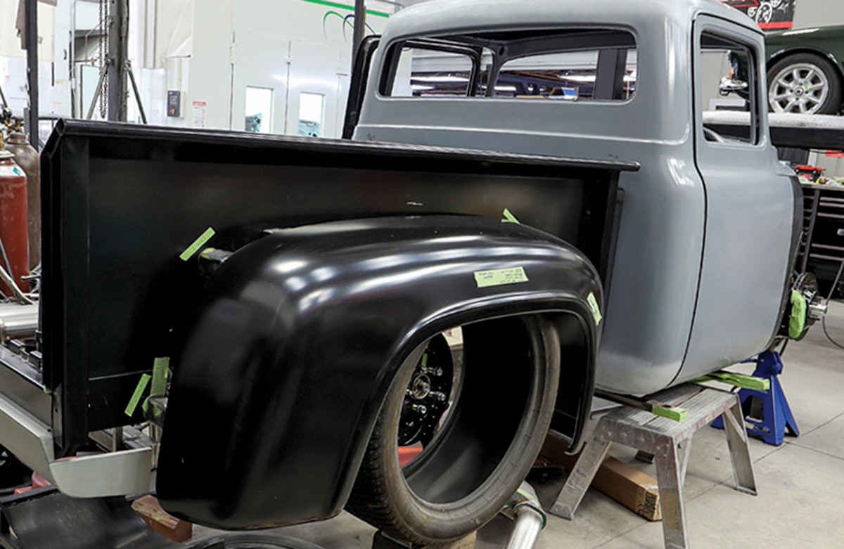
t’s been many months since we checked on the progress of the Souza F-100 being built at Gary’s Rods & Restorations. We think you’ll love seeing the work done on the bed, which is largely handmade, with a design that follows the contours of the cab. The outer portion of the rear fenders will stand proud of the contoured bedsides, so it will have a unique character—bringing traditional Ford styling into the modern era. Emilio Belmonte is the primary fabricator on this project, and as you’ll see, the work is done to a very high level.

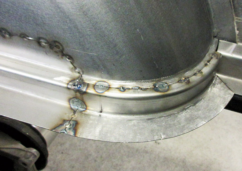
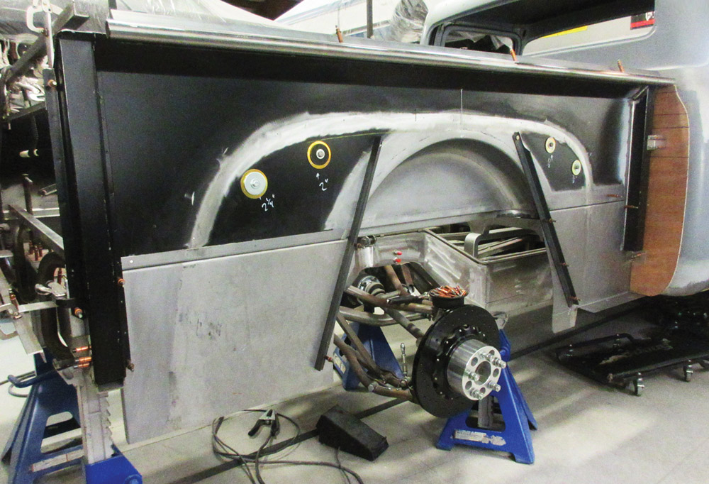
A reproduction bed and rear fenders were sourced from LMC but they will be highly modified. The original bed was spaced about 1-1/2 inches away from the cab in the center, and with the curvature of the cab that left a sizable gap on each side. Extensions were made for the front of the bed so it closely follows the cab contours, and a piece of 1-1/4-inch round tubing was bent to cap the double walls at the front edge. The wide rear tires required inner wheelwells that were carefully shaped from new metal.

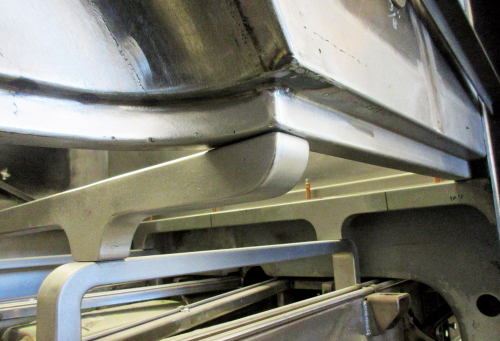
The original bed mounts were very basic, so new ones were made to follow the elegant character of this truck. The mounts started as lengths of rectangular tubing, which were scalloped away and beautifully finished, producing an elegant design.

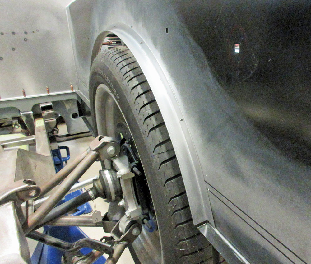
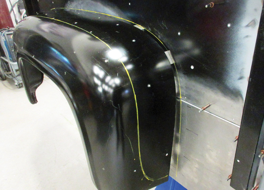
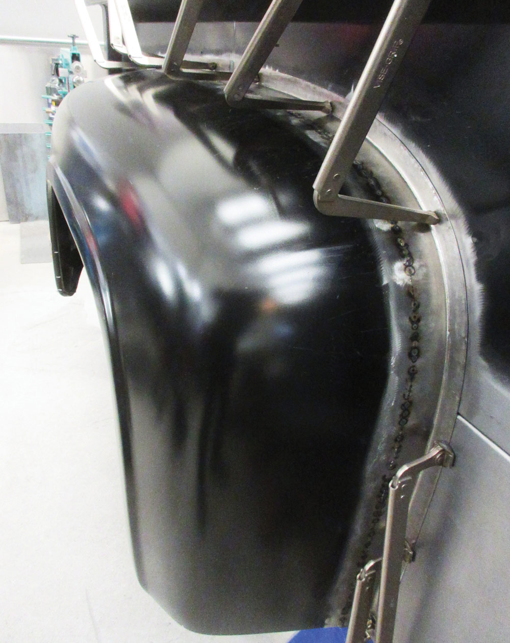
The rear fenders were moved out from the bed to provide adequate clearance for the rear wheels and tires, requiring new mounting flanges to be fabricated. The original flanges pointed inward, but the new flanges go outward to provide more wheel clearance.

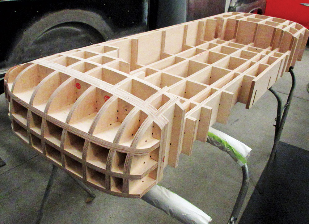
With the bed and fenders mounted, the mock-up of the new bedsides could begin. Everything was scanned first, providing a baseline for the design, then blocks of foam insulation were hand-shaped by eye and masking tape was used to fill in some of the highly curved open areas. The idea was to follow the contour of the cab sides but inset the bedsides a couple of inches. Once the basic shapes were worked out, Sean Sinnott from Designer Grains was called in to model the entire bed in CAD and do the refinement of the shape on his computer.

Once the design was finalized and approved by the owner, Sinnott CNC routed sheets of 3/4-inch plywood to make accurate bucks for the bedsides. We’ll see the shaping of the outer bed in a future article, but the photos here show a wealth of detail you’re sure to enjoy.

Close-up of a weld seam in the custom fabrication of the F-100's bed structure
2. The reproduction bed from LMC was flat on the front edge. Like the stock bed, it was spaced a generous distance from the cab. The top corner of the bed has been filled in here to tighten the gap.
Interior metalwork showcasing precision welding on the F-100's custom bed panels
3. A new piece of metal was cut for the front bed panel. Flanges were formed to move the panel forward and to space the welds away from the corner so any distortion from welding can be hammered out.
A side view of the F-100 bed with fitted custom inner wheel housings
4. The front panel inside the bed is flat, and a second panel was made, facing the cab, which closely follows its contour.
Fabrication clamps securing a custom panel on the F-100 bed for precision fitting
5. A piece of 1-1/4-inch-diameter tubing was contoured to match the curvature of the cab and to finish the top surface of the front bed panels.
A wooden template designed for the custom wheel arches on the F-100 bed
6. The rear tires are much larger than stock, so the bedsides were cut away to provide clearance. A piece of 1/2-inch MDF is cut to the size required for the inner wheelwell.
Using a JS-Tools metal shrinker to shape metal panels for the F-100's wheel arch
7. A piece of 16-gauge sheetmetal is bent into an angle and worked with a stretching machine, curving it to match the contour of the wheelwell.
Completed custom metal wheel arch sections laid next to the template for the F-100
8. One curved angle is needed for each side of the bed.
Test fitting the newly fabricated wheel arches around the tires on the F-100 bed
9. The angles are held temporarily to the bed with Clecos. The suspension is in full bump here, making sure the inner wheelwell will have plenty of clearance.
Shaping the metal arch for the F-100 using a custom guide and shrinker tool
10. The majority of the wheelwell is shaped from a single piece of 18-gauge steel using a deep-throat shrinker. The grid pattern helps keep the shrinking pattern uniform. The inner portion of the wheelwell is sandwiched between sheets of MDF to help keep it flat.
Custom metal wheel tub shaped for the 1953-1956 Ford F-100 bed
11. You can see how closely the inner portion of the wheelwell matches the perimeter. They will be clamped together on the bed, then scribed, trimmed, and welded together.
Metal arch with laser alignment for precision during fabrication
12. The two major pieces of the wheelwell have been welded and metalfinished, and a laser level is used to position the Z-shaped edge on the bottom of the wheelwell.
Spot welding the custom wheel tub onto the F-100 bed structure
13. A filler piece is added to the rounded corners of the wheelwell.
Cut and shaped metal parts prepared for assembly
14. New braces were made to mount the bed to the chassis. Here you can see the lengths of 2×4-inch steel tubing that have been notched out, and the filler pieces that are prepped for boxing in the recesses.
Fabricating custom support beams for the F-100 bed frame
15. The brace is clamped to a tube to help keep it straight as the filler pieces are welded into place.
Completed custom cross members for the F-100 bed chassis
16. All the joints are sanded smooth here. You can see the finish work is taken to a very high level, even on parts that won’t be easily seen.
Cross member support structure installed beneath the F-100 bed
17. Here’s how the elegant braces connect the bed to the chassis.
Rear view of the custom-fabricated F-100 bed with wheel tubs and suspension visible
18. New panels are made from 16-gauge sheetmetal to extend the bottom edges of the bed.
Test-fitting the outer fender on the custom F-100 bed structure
19. The rear fenders are spaced out about 2-1/2 inches in the front and 3-1/4 inches in the rear to give the rear tires sufficient clearance. The dots on the panel are to aid the scanning, which will provide data points for modeling the new bedsides.
Rear fender mounted on a custom vehicle build
20. Angles are made from 18-gauge sheetmetal and then shaped with a shrinker and stretcher to match the contours of the fenders.
Side view of the fender clamped for fitting
21. The shaped angles are trimmed to size and tack welded to the fenders. The mounting flanges point away from the tires to give the needed clearance.
Unpainted rear fender in fabrication, attached to the vehicle
22. The welded joints are metalfinished to perfection.
Custom truck bed panel with foam padding and tape for protection
23. Insulation foam is used here to mock up the shape of the bedside. It will follow the contours of the cab but be inset a couple of inches.
Wooden grid framework likely used for shaping or supporting parts
24. Using data from the scans of the bed and the foam mock-up, 3/4-inch plywood was cut with a CNC router to make the pieces for bucks, which will be used for shaping the new bedsides. Look forward to an article that will cover this in the near future!
SOURCES