CTP  Tech

InTheGarageMedia.com

Presto-Chango!
1. The project at hand involves using the lip edge design from the front fender of a ’63 C-1100 International Harvester pickup and transplanting it to the rear fenders.
Old Anvil Works its Magic on an International Fender
BY Eric GeisertPhotography BY THE AUTHOR
Y

ou know how when you ask a 5-year-old to draw a cow or dog their sketch is usually way out of proportion, with legs too long or head too small but always with really big eyes? That’s the way some people see the ’60s-era International Harvester line of pickup truck—it kinda looks way out of proportion. 

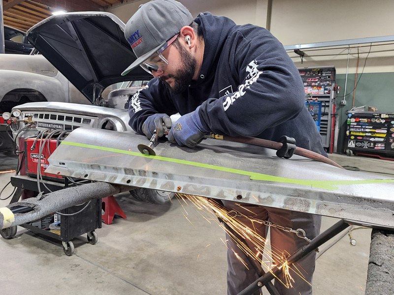
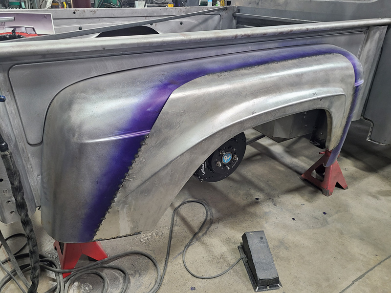
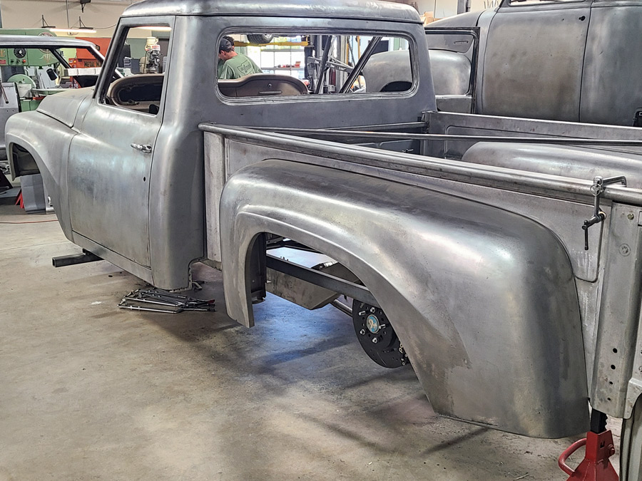
Classic Truck Performance stopped by Old Anvil Speed Shop in Orange, California, to see what they’re doing about it with one of their customer’s projects: a ’63 C-1100 International Harvester standard-wheelbase Stepside pickup.

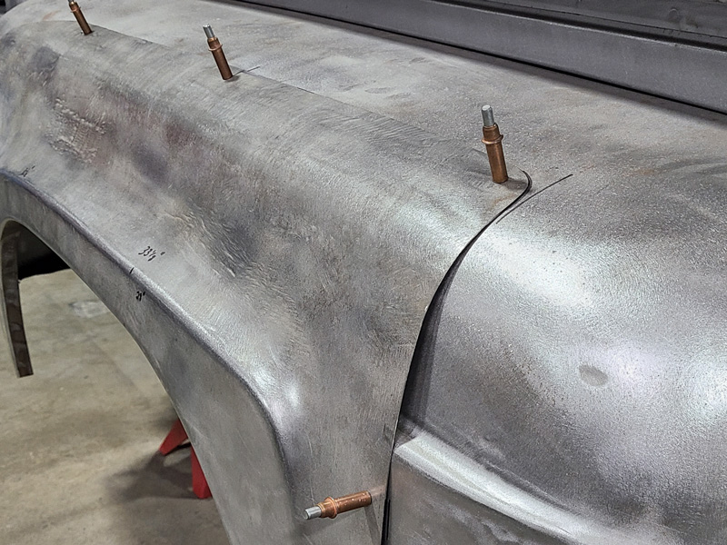
Two of Old Anvil’s principals (owner Paul Bosserman and graphic artist Jeff Allison) teamed up to heavily massage this International Harvester pickup and knock some of the weirdness off. The truck is benefiting from a long list of custom bodywork they worked out together, including reshaping the grille area and roofline, but something had to be done about the bed’s fenders—they’re just too plain. 

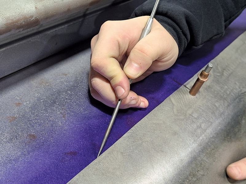
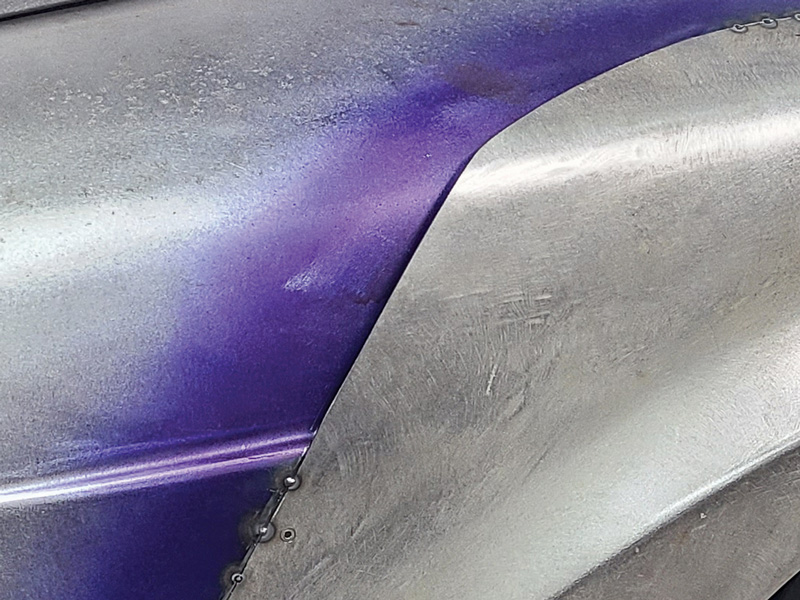
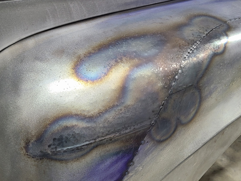
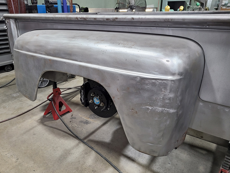
The front fenders have this large, scalloped flare design that makes a statement, but the rears, with a simple, thin body line (reminiscent of a ’50 Ford F-1 rear fender’s lowkey look) looks anemic on a truck with so much personality elsewhere. So the idea was hatched to carry the front fender’s flarelip design into the rear fenders, and CTP followed along as one of Old Anvil’s young metalshapers, Brandon Gerringer, took the idea from concept to reality.

For as flamboyant as the front end of the truck is, the stock rear fenders are positively sedate in comparison.
2. For as flamboyant as the front end of the truck is, the stock rear fenders are positively sedate in comparison.
 In a proof of concept, one of the spare front fenders was cut apart and Cleco’d to the existing fender to get a rough idea what the fender might end up looking like.

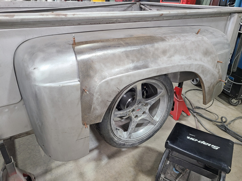
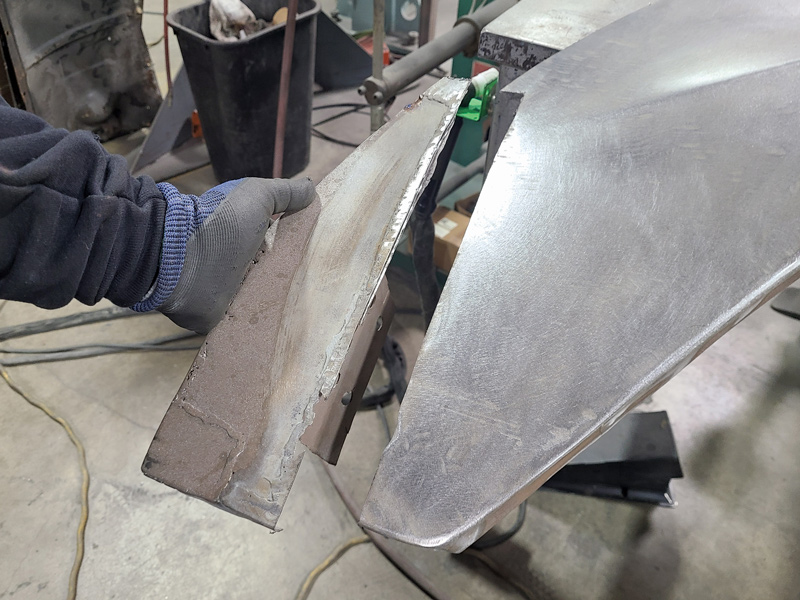
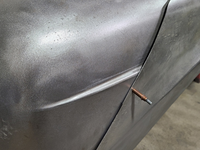
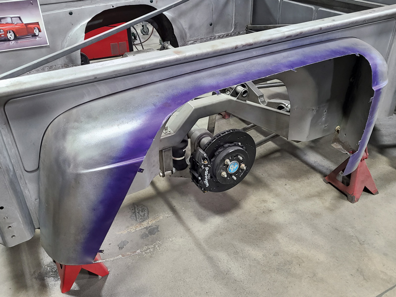
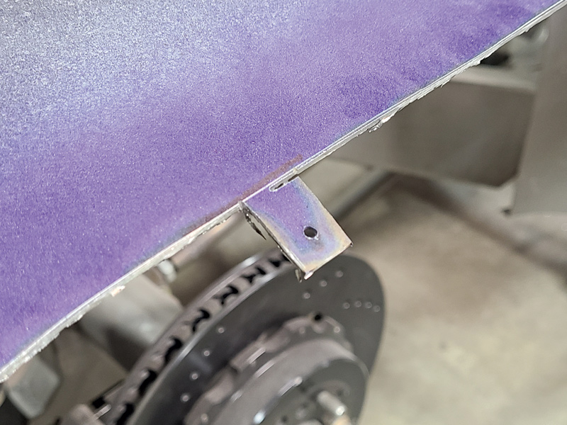
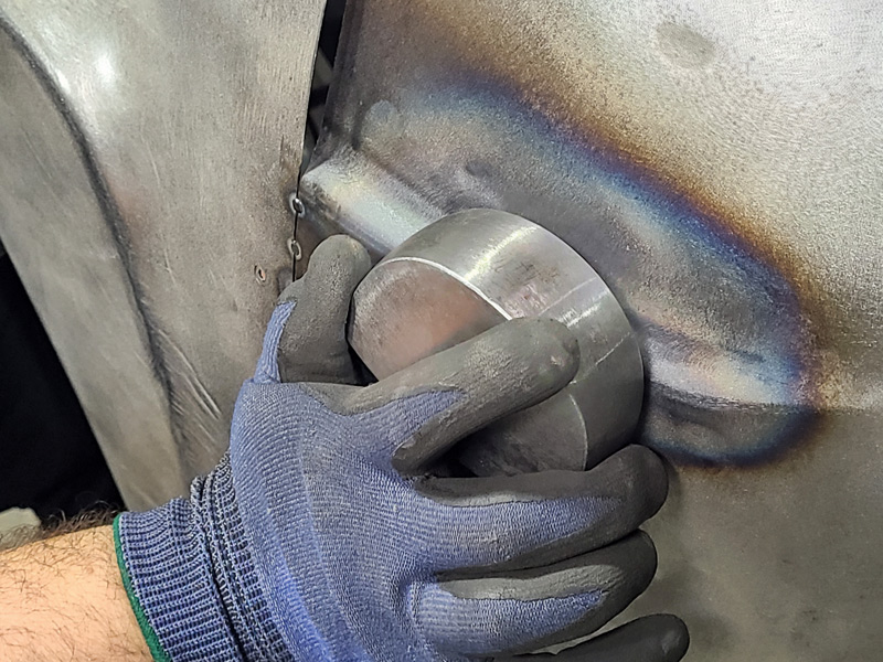
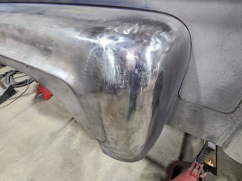
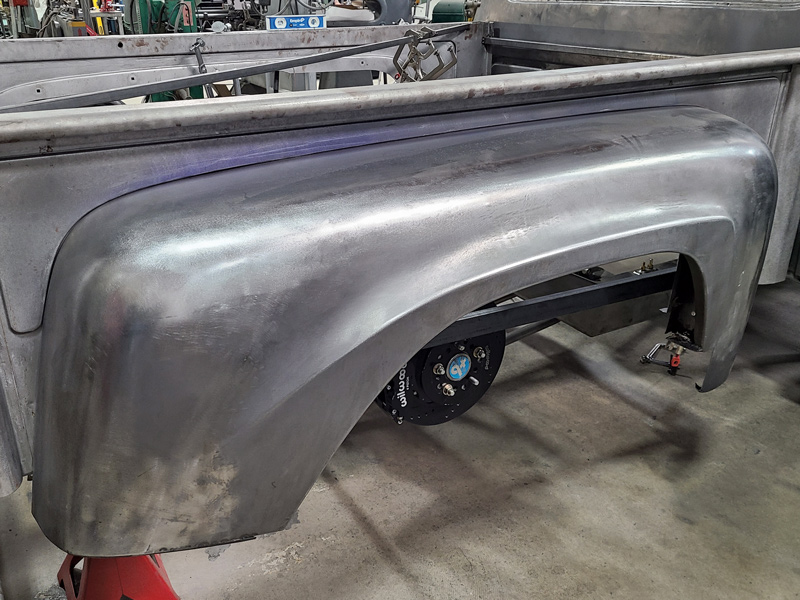
3. In a proof of concept, one of the spare front fenders was cut apart and Cleco’d to the existing fender to get a rough idea what the fender might end up looking like.

Some of the donor front fender sections are cut off as they won’t be needed.
4. Some of the donor front fender sections are cut off as they won’t be needed.
Some rust repair work was also needed, so Brandon Gerringer removed the old section and then formed a new piece before clamping and welding them together. The piece was intentionally left long as some areas of the fender’s new design were still being worked out.
5-6. Some rust repair work was also needed, so Brandon Gerringer removed the old section and then formed a new piece before clamping and welding them together. The piece was intentionally left long as some areas of the fender’s new design were still being worked out.
After slightly bending the panel over his knee to get the shape started, Gerringer then runs the part through the planishing hammer in an East-West then North-South direction, but it also helps flatten the welds.
7. After slightly bending the panel over his knee to get the shape started, Gerringer then runs the part through the planishing hammer in an East-West then North-South direction, but it also helps flatten the welds.
 Another rough cut line is marked and some of the original fender surface is removed so the new section will fit better.
8. Another rough cut line is marked and some of the original fender surface is removed so the new section will fit better.
With the old fender opened up, the new fender section can now lay down on the old fender and get prepped for final cutting.
9. With the old fender opened up, the new fender section can now lay down on the old fender and get prepped for final cutting.
For the driver side fender Gerringer had picked out the precise location of the new fender section by simply moving it around until it looked “right.” But the passenger side needed to copy the other side, so the new section was Cleco’d in and a handful of measurements were taken to ensure both fenders would fit the bed box in the same way.
10. For the driver side fender Gerringer had picked out the precise location of the new fender section by simply moving it around until it looked “right.” But the passenger side needed to copy the other side, so the new section was Cleco’d in and a handful of measurements were taken to ensure both fenders would fit the bed box in the same way.
The gaps between the old fender design and the new sections were going to be the areas that were going to need the most attention on this job.
The gaps between the old fender design and the new sections were going to be the areas that were going to need the most attention on this job
11-12. The gaps between the old fender design and the new sections were going to be the areas that were going to need the most attention on this job.
The old fender was sprayed with Dykem layout fluid and the new section Cleco’d back on before Gerringer scribed where the cut line was going to be.
13. The old fender was sprayed with Dykem layout fluid and the new section Cleco’d back on before Gerringer scribed where the cut line was going to be.
In order to remove and reattach the fender several times during the process Gerringer incorporated mounting tabs for the Clecos.
14. In order to remove and reattach the fender several times during the process Gerringer incorporated mounting tabs for the Clecos.
Using a 1/16-inch cutoff wheel, Gerringer cuts along this line and removes the last part of the old fender.
15. Using a 1/16-inch cutoff wheel, Gerringer cuts along this line and removes the last part of the old fender.
The Cleco mounting tabs are still in place.
16. The Cleco mounting tabs are still in place.
 With the new section mounted you can see the tiny gap that will need to be welded up.
17. With the new section mounted you can see the tiny gap that will need to be welded up.
 Because the bottom section of the fender’s design hasn’t been settled yet, Gerringer can only go so far while tacking the bottom of the leading edge.
18. Because the bottom section of the fender’s design hasn’t been settled yet, Gerringer can only go so far while tacking the bottom of the leading edge.
Every 1/2-inch or so Gerringer tacks the two pieces together, except in the areas that still need to be worked further.
19. Every 1/2-inch or so Gerringer tacks the two pieces together, except in the areas that still need to be worked further.
The idea of adding the front fender lip to the rear shows promise, but now hard work begins on the two gap areas.
20. The idea of adding the front fender lip to the rear shows promise, but now hard work begins on the two gap areas.
 Starting with the front area, Gerringer uses a MAP/PRO torch to superheat the stamped line before quickly using a hammer (inside) and dolly (outside) to begin flattening it out.
 Starting with the front area, Gerringer uses a MAP/PRO torch to superheat the stamped line before quickly using a hammer (inside) and dolly (outside) to begin flattening it out.
21-22. Starting with the front area, Gerringer uses a MAP/PRO torch to superheat the stamped line before quickly using a hammer (inside) and dolly (outside) to begin flattening it out.
 Going from using a sandbag (outside) and a ball peen hammer (inside) to a hammer (outside) and dolly (viewed from inside the fender), Gerringer alternates between raising and lowering the sections until they begin to meet each other
 Going from using a sandbag (outside) and a ball peen hammer (inside) to a hammer (outside) and dolly (viewed from inside the fender), Gerringer alternates between raising and lowering the sections until they begin to meet each other.
23-24. Going from using a sandbag (outside) and a ball peen hammer (inside) to a hammer (outside) and dolly (viewed from inside the fender), Gerringer alternates between raising and lowering the sections until they begin to meet each other.
 As the sections get very close to each other Gerringer begins to tack weld them together—a little at the bottom, then the top, then back to the bottom.
25. As the sections get very close to each other Gerringer begins to tack weld them together—a little at the bottom, then the top, then back to the bottom.
 A hoop-type pneumatic planishing hammer also helps to flatten and shape the areas that need it.
26. A hoop-type pneumatic planishing hammer also helps to flatten and shape the areas that need it.
 Gerringer fab’d the steel tool in his left hand on the lathe (adding some knurling, too) that holds one of the planishing hammer dies so he can precisely hand planish some of the areas
27. Gerringer fab’d the steel tool in his left hand on the lathe (adding some knurling, too) that holds one of the planishing hammer dies so he can precisely hand planish some of the areas
The area that contained the gap and the old fender detail is now gone.<br />
28. The area that contained the gap and the old fender detail is now gone.
The same type of intensive bodywork was applied to the rear section with the same stunning result (though the application of heat was a bit wider this time as the transition needed to run over a wider area) and more shrinking and stretching needed to happen.
29-30. The same type of intensive bodywork was applied to the rear section with the same stunning result (though the application of heat was a bit wider this time as the transition needed to run over a wider area) and more shrinking and stretching needed to happen.
 After final welding, planishing, and sanding the “new” fender design can now be revealed.
31. After final welding, planishing, and sanding the “new” fender design can now be revealed.
 From any angle you can now see how the front fender’s lip has been transplanted to the rear fender, too, and we wonder why the factory never thought of doing that because the truck’s profile has been greatly improved.
32. From any angle you can now see how the front fender’s lip has been transplanted to the rear fender, too, and we wonder why the factory never thought of doing that because the truck’s profile has been greatly improved.