CTP  Tech

InTheGarageMedia.com

Changes for the Better
Joe McGlynn’s “Dream Stude”
BY Ron CovellPhotography BY THE AUTHOR
J

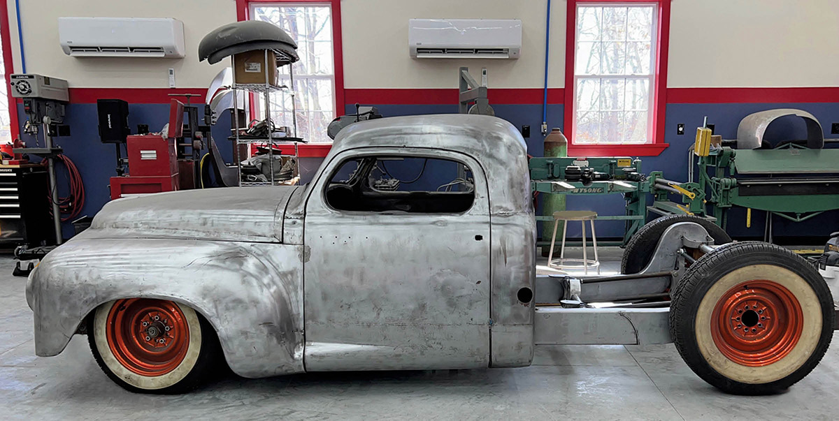
oe McGlynn is working on a very cool project: a chopped and sectioned ’56 Studebaker pickup inspired by the famous Rod & Custom Dream Truck. While he’s not building a clone, it does incorporate some major styling themes from that historic project.

McGlynn started this truck many years ago, but then “life got in the way” and his progress was halted for several years. After moving from California to Missouri and building his dream shop on his property, the truck project was finally revived.

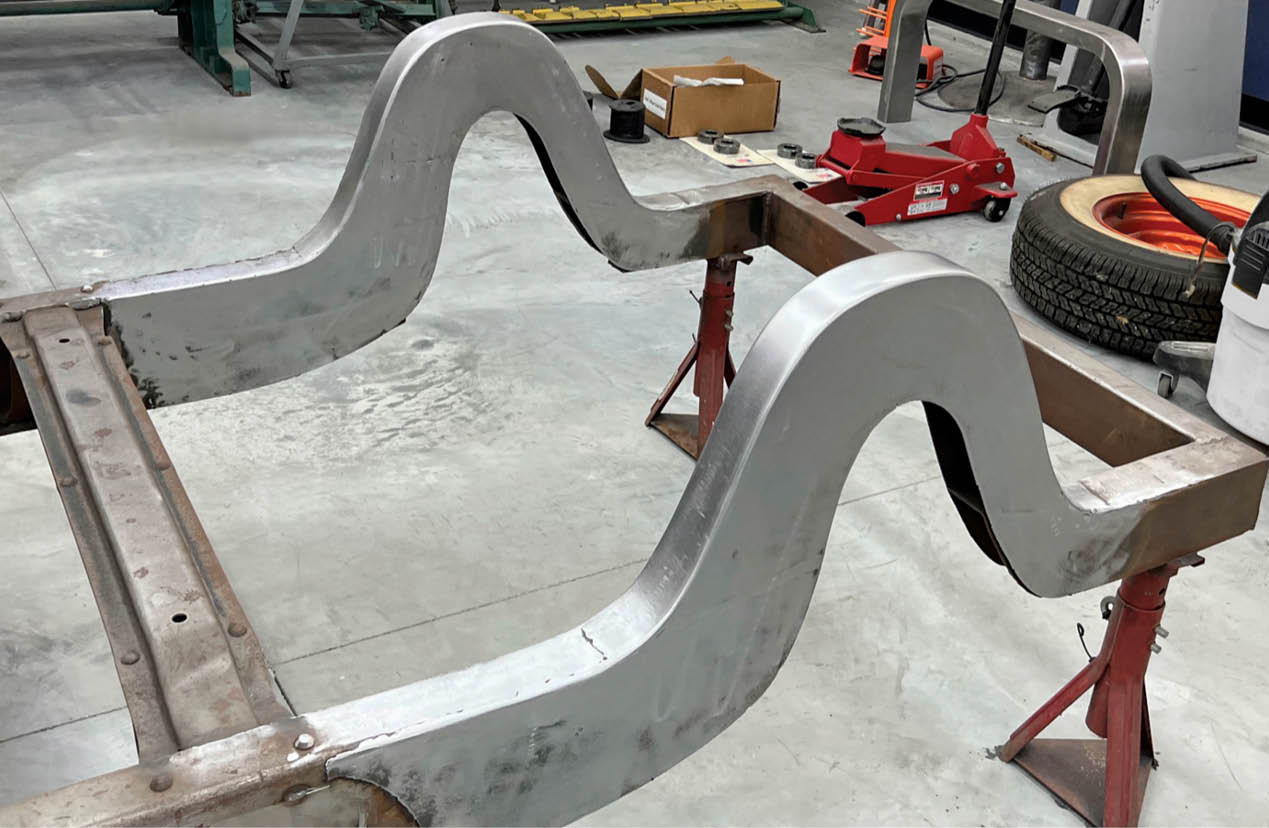
Over the years, McGlynn’s tastes have become more sophisticated, so in Version 2.0 of this project, he decided to revise some of the initial work. The truck will feature a completely custom-built bed. He realized the rear wheels were a bit too wide for his design. Unfortunately, the four-link suspension outside the framerails prevented him from moving the wheels in as much as needed.

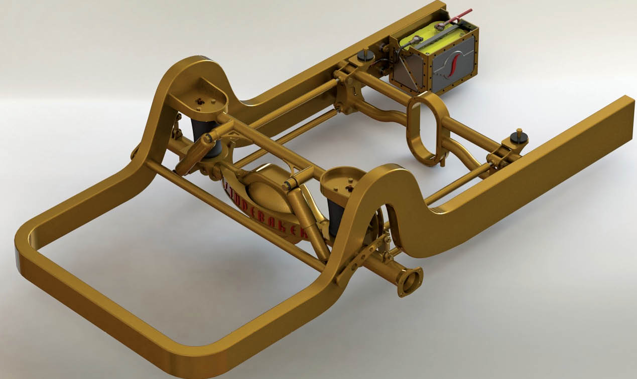
This required a complete redesign of the rear chassis and suspension, which McGlynn modeled in CAD. Having a digital model not only allowed him to fine-tune all the necessary dimensions, he could also examine the clearances in the “tight” areas and could send digital files out to have many of the components precisely laser cut. This was done by a company named SendCutSend, which saved an enormous amount of time in the fabrication process. It also allowed him to work to very precise tolerances.

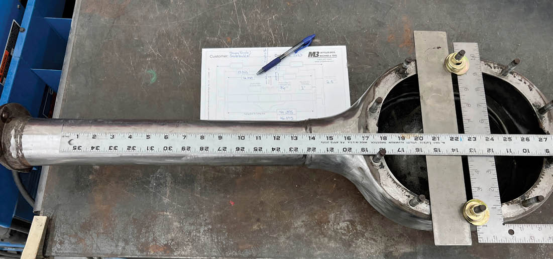
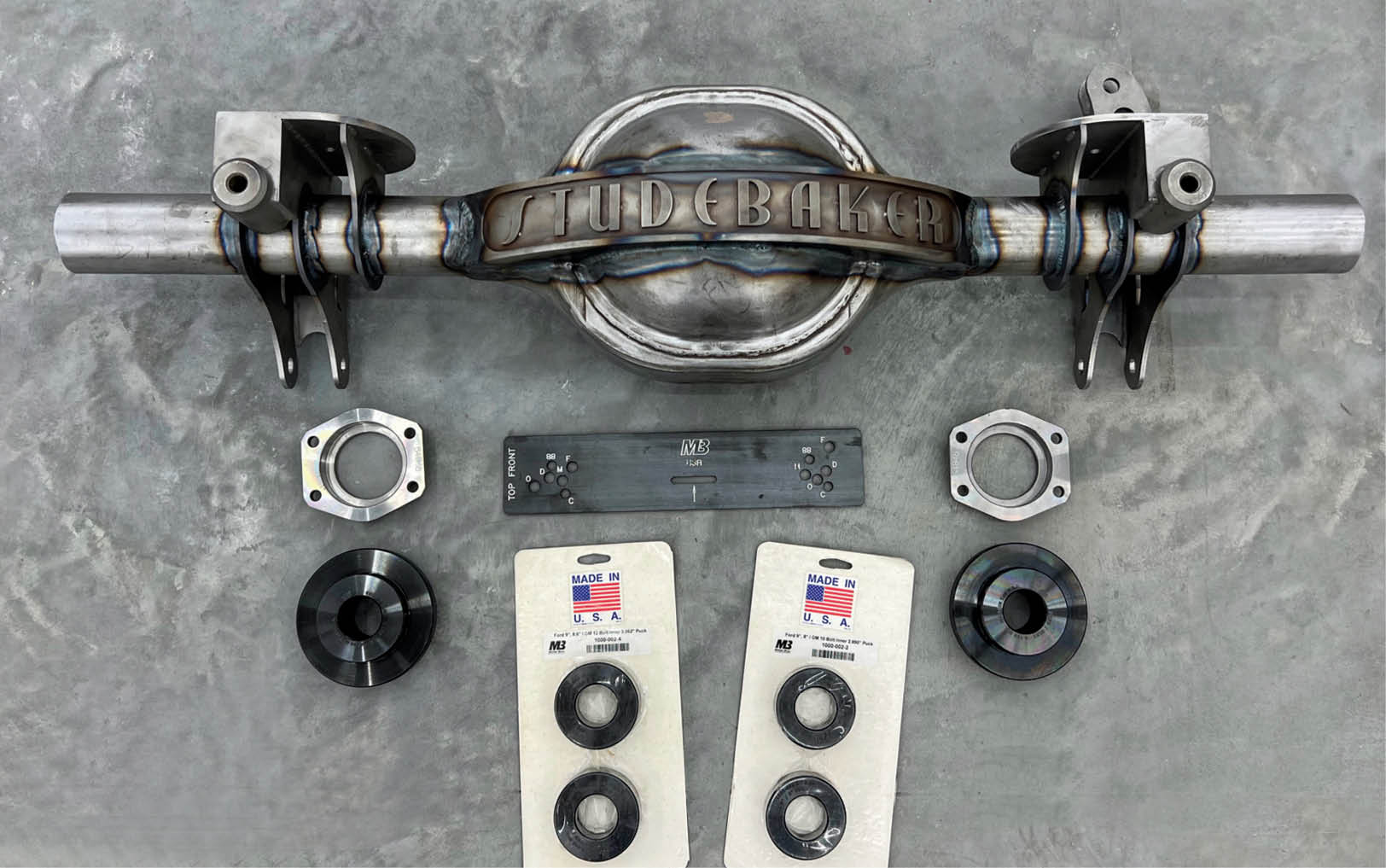
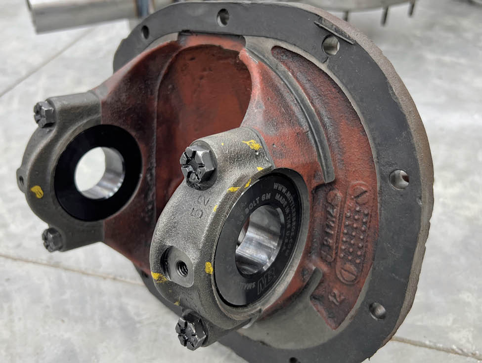
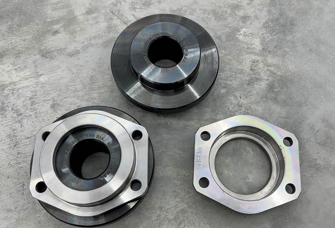
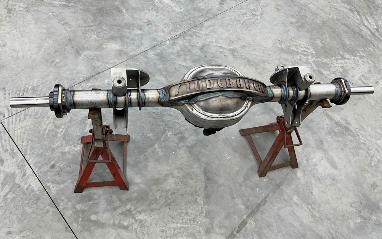
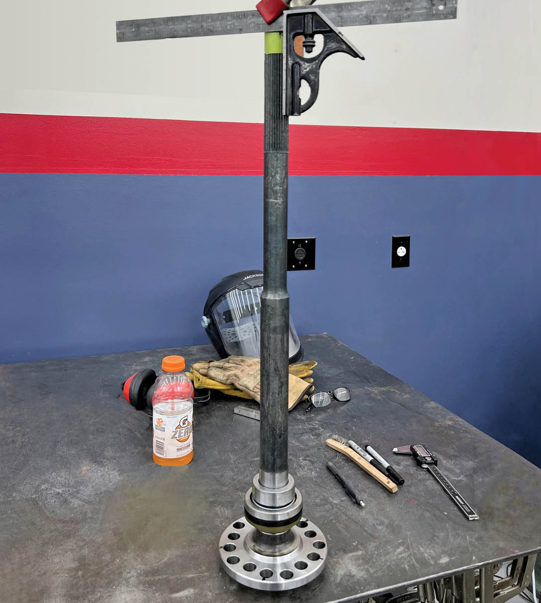
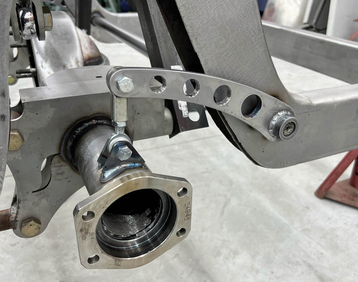
McGlynn used a Narrowing Kit from Mittler Bros. to keep the axle bearings accurately aligned when he narrowed the rearend. This kit has sleeves that go in the bearing blocks in the third member and in the outer bearing housings. A precision-ground shaft fits through all these sleeves, precisely aligning the outer bearings before welding. It is essential to weld all of the brackets to the axle housing before installing the outer bearings since the welding on the brackets will distort the axle tubes.

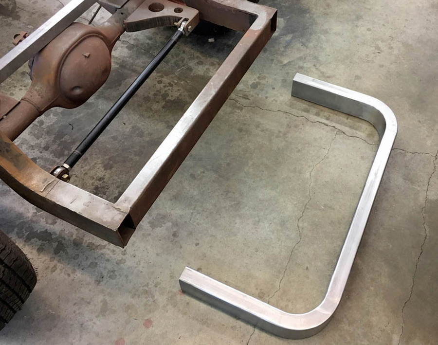
Another product that proved quite helpful is the kit from Paul Horton’s Welder’s Series, which created the beautifully rounded corners where the rear crossmember connects to the framerails. This provides the same look as mandrel-bent tubing, but you can accomplish the task in your own garage.

As you look through the photos, you will appreciate many ways the latest technology can offer help for the homebuilder.

This is a CAD rendering Joe McGlynn made detailing the changes he planned for the chassis of his project truck.
1. This is a CAD rendering Joe McGlynn made detailing the changes he planned for the chassis of his project truck.
The rearend was originally set up with the four-link system outside the framerails. This prevented McGlynn from narrowing the rearend as much as he needed so changes were required.

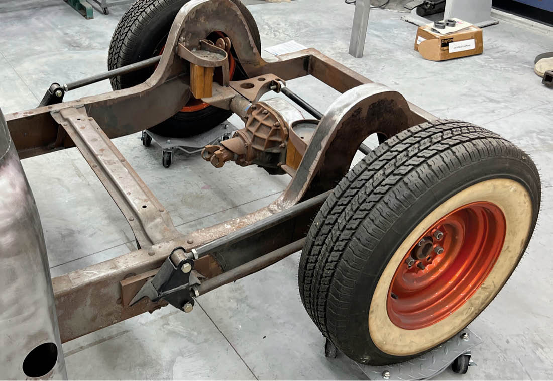
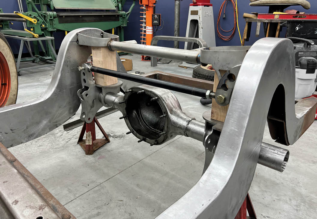
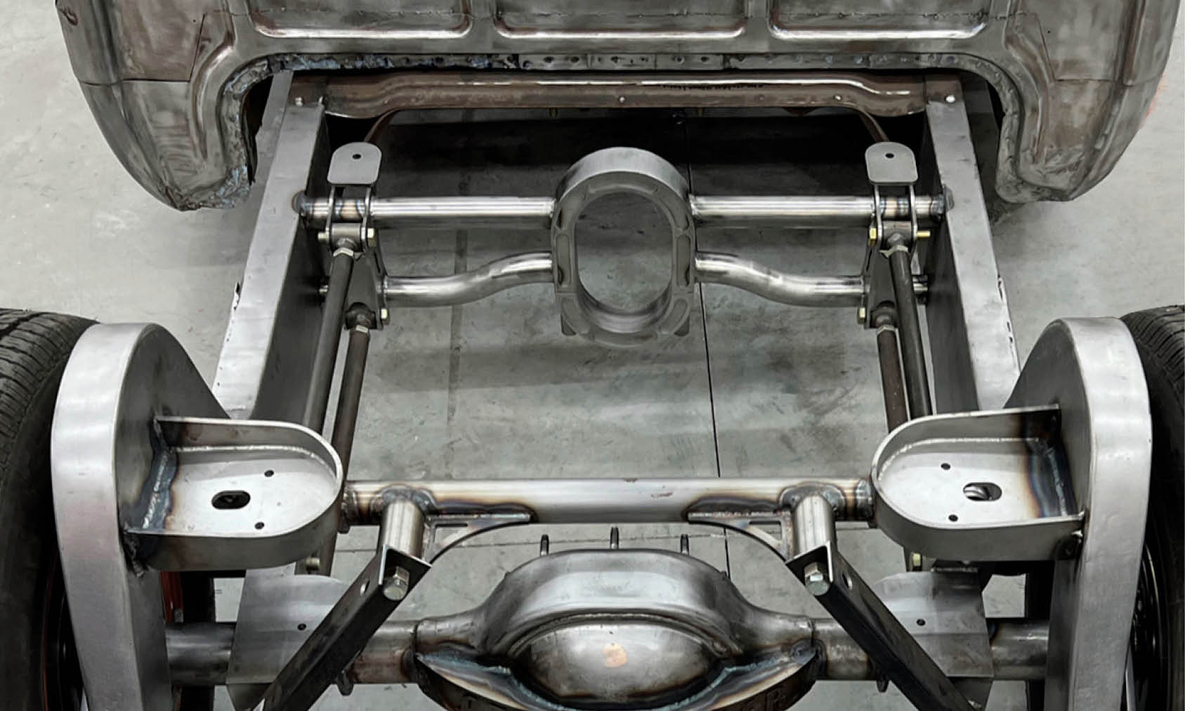
2. The rearend was originally set up with the four-link system outside the framerails. This prevented McGlynn from narrowing the rearend as much as he needed so changes were required.

The new plan was to run the four-link system inside the framerails. All the brackets and the crossmember for the rear suspension were removed from the chassis.
3. The new plan was to run the four-link system inside the framerails. All the brackets and the crossmember for the rear suspension were removed from the chassis.
The rearend housing was stripped of all its brackets and cleaned in preparation for being narrowed the desired amount.

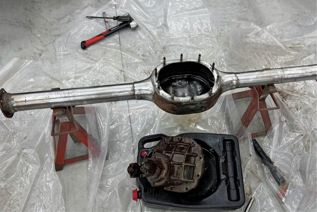
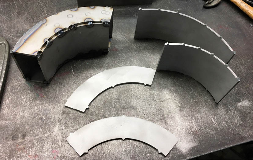
4. The rearend housing was stripped of all its brackets and cleaned in preparation for being narrowed the desired amount.

All of the brackets for the rear suspension and crossmembers were CAD designed and sent out for laser cutting.
5. All of the brackets for the rear suspension and crossmembers were CAD designed and sent out for laser cutting.
The laser-cut pieces were fitted together, checked for squareness, and welded into sub-assemblies.

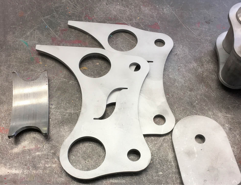
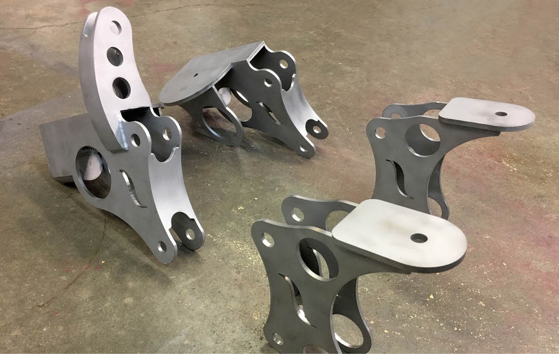
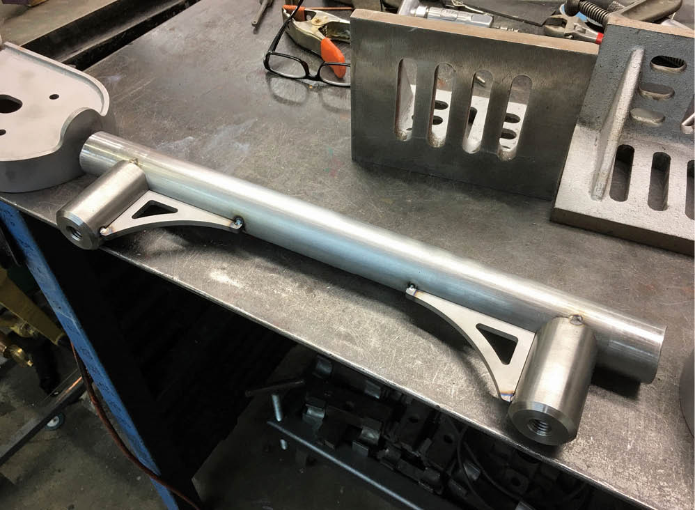
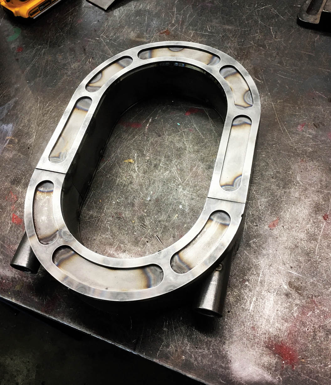
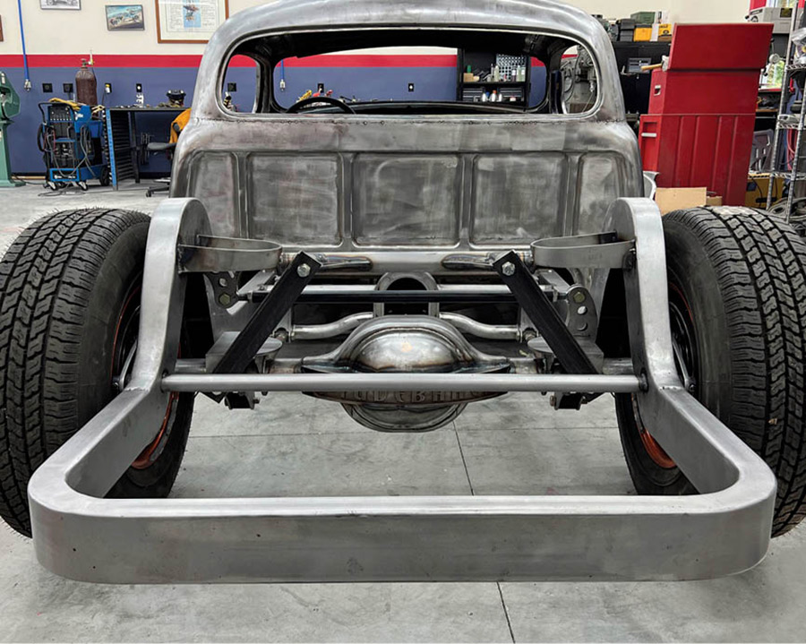
6. The laser-cut pieces were fitted together, checked for squareness, and welded into sub-assemblies.

Normally the third member is offset to place the driveshaft in the center of the vehicle. McGlynn wanted the third member to be centered so careful measurements were made to locate the cuts on the axle housing.
7. Normally the third member is offset to place the driveshaft in the center of the vehicle. McGlynn wanted the third member to be centered so careful measurements were made to locate the cuts on the axle housing.
A brace featuring the Studebaker logo was designed for the rear of the axle housing. Again, all the parts were CAD designed and laser cut, saving many hours of fabrication time.

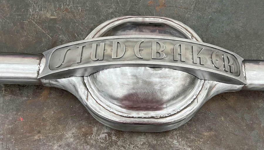
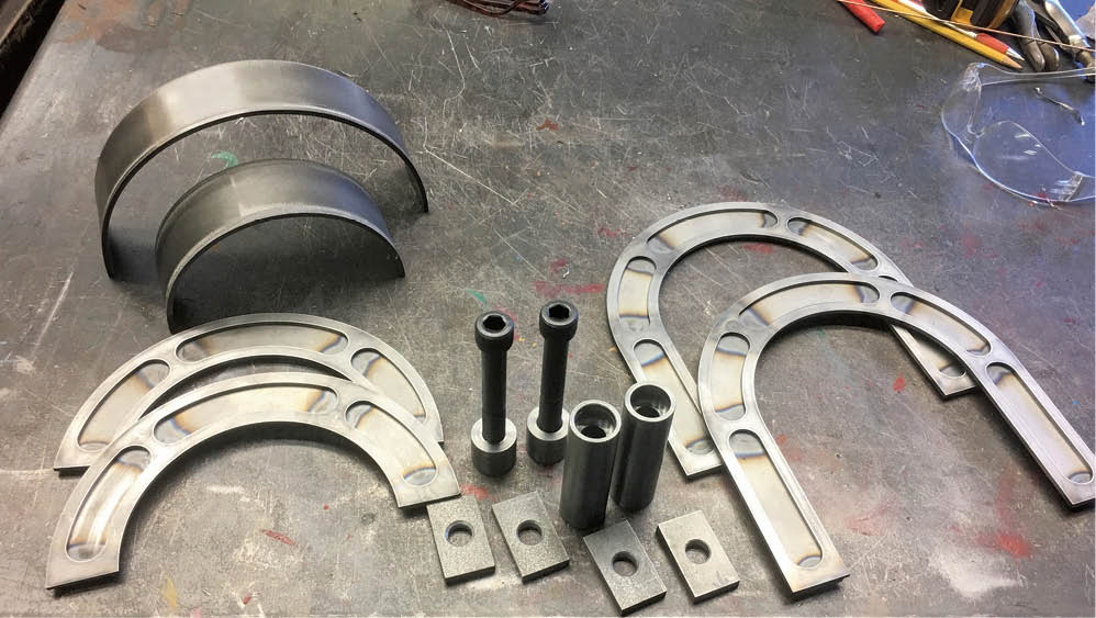
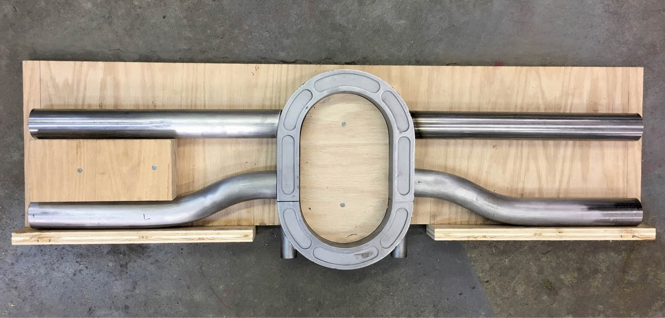
8. A brace featuring the Studebaker logo was designed for the rear of the axle housing. Again, all the parts were CAD designed and laser cut, saving many hours of fabrication time.

The ends were trimmed off the axle housing and the brackets were slipped into place. After careful fitting they were finish welded. Some components of the Mittler Bros. axle narrowing kit are shown.
9. The ends were trimmed off the axle housing and the brackets were slipped into place. After careful fitting they were finish welded. Some components of the Mittler Bros. axle narrowing kit are shown.
The Mittler narrowing kit has sleeves that fit in the third member bearing blocks. These hold a precision-ground shaft that positions the outer bearing bosses with perfect alignment.
10. The Mittler narrowing kit has sleeves that fit in the third member bearing blocks. These hold a precision-ground shaft that positions the outer bearing bosses with perfect alignment.
These are the sleeves that fit in the outer bearing bosses.
11. These are the sleeves that fit in the outer bearing bosses.
With the shaft fitted through the sleeves in the third member, the outer bearing bosses can be slipped into place and welded. This ensures precise alignment of all the axle bearings.
12. With the shaft fitted through the sleeves in the third member, the outer bearing bosses can be slipped into place and welded. This ensures precise alignment of all the axle bearings.
McGlynn thought he would need to have new axles made until he learned that Speedway Motors supplies axles with extra-long splines that can be easily cut to length.
13. McGlynn thought he would need to have new axles made until he learned that Speedway Motors supplies axles with extra-long splines that can be easily cut to length.
These components for the rear suspension crossmember are being preassembled on the bench.
14. These components for the rear suspension crossmember are being preassembled on the bench.
The rear axle crossmember is carefully positioned and tack welded into place. Wooden blocks are used here to stand in for the airbags at normal ride height.
15. The rear axle crossmember is carefully positioned and tack welded into place. Wooden blocks are used here to stand in for the airbags at normal ride height.
These are the laser-cut components for the driveshaft loop, which goes in the center of the crossmember just ahead of the rearend.
16. These are the laser-cut components for the driveshaft loop, which goes in the center of the crossmember just ahead of the rearend.
All the components for the driveshaft loop have been assembled. Note that the lower portion is removable, making it easy to install and remove the driveshaft.
17. All the components for the driveshaft loop have been assembled. Note that the lower portion is removable, making it easy to install and remove the driveshaft.
A simple plywood fixture was made to properly align all the components for the crossmember for welding.
18. A simple plywood fixture was made to properly align all the components for the crossmember for welding.
Here the suspension crossmember is welded into place. This is an exceptionally clean and strong installation.
19. Here the suspension crossmember is welded into place. This is an exceptionally clean and strong installation.
The former rear crossmember had square corners but McGlynn decided to blend it in with a nice radius. He got these weld-it-yourself corners from Paul Horton that are sized perfectly for 2x4 rectangular tubing.
20. The former rear crossmember had square corners but McGlynn decided to blend it in with a nice radius. He got these weld-it-yourself corners from Paul Horton that are sized perfectly for 2×4 rectangular tubing.
Here’s a side-by-side comparison of the old and new rear crossmember.
21. Here’s a side-by-side comparison of the old and new rear crossmember.
With the new rear crossmember welded into place and the welds ground smooth we think you’ll agree it’s a big improvement over the previous version.
22. With the new rear crossmember welded into place and the welds ground smooth we think you’ll agree it’s a big improvement over the previous version.
McGlynn fit a stabilizer bar inside a round tube positioned just behind the rear axle. The arms were CAD designed and laser cut. This makes a very clean installation.
23. McGlynn fit a stabilizer bar inside a round tube positioned just behind the rear axle. The arms were CAD designed and laser cut. This makes a very clean installation.
Here’s a shot of the truck showing the cab and front end. You can see the all-over proportions of the truck here showing the 4-inch chop and the 6-inch section.
24. Here’s a shot of the truck showing the cab and front end. You can see the all-over proportions of the truck here showing the 4-inch chop and the 6-inch section.
 SOURCES
MITTLER BROS.
(636) 745-7757
mittlerbros.com
Paul Horton’s Welder Series
(888) 648-2150
welderseries.com
SendCutSend
(775) 683-9499
sendcutsend.com
Speedway Motors
(855) 313-9176
speedwaymotors.com/classictruckperformance