Tech
InTheGarageMedia.com
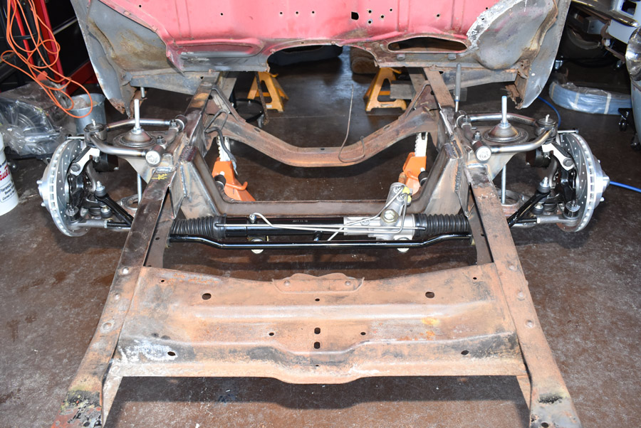
1. With the Heidts frontend installed we did a quick and dirty temporary alignment with a tape measure and our Speedway Motors caster/camber gauge. Adjustments will be made more accurately before the truck hits the road.
Independence for all
Heidts IFS for ’50s
Ford F-100s

BY Ron Ceridono  Photography By The Author

O

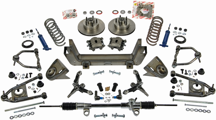
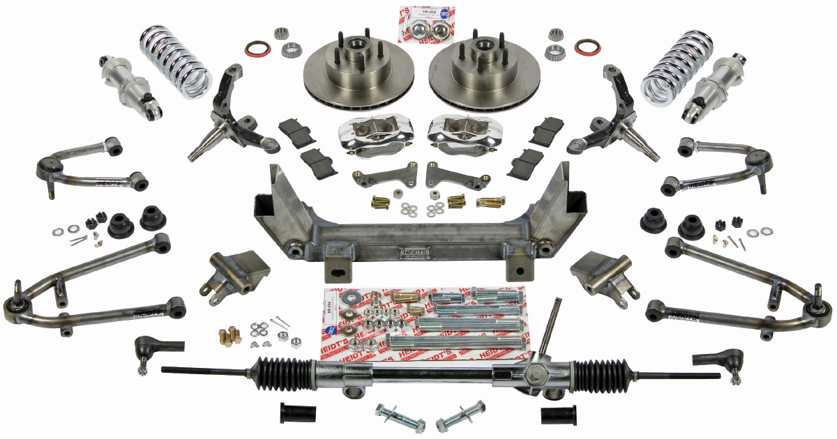
f all the products that have been offered to improve the overall performance of hot rods and classic trucks, arguably, Mustang II–based independent front suspension kits have to be high up on the list. Simple, affordable, and effective, these suspension packages make it easy to transform a rough-riding, solid-axle truck into a smooth-riding, better-handling version of itself. In addition to the advantages IFS offers compared to a solid front axle, there are a few other perks, such as the modern disc brakes and rack-and-pinion steering, that are also part of the package. The suspension swap shown here was done on a 1955 Ford F-100, but the procedure is virtually the same for any solid-axle pickup. We chose a Heidts PX-105-E-K IFS kit that uses coil springs, power rack-and-pinion steering, and disc brakes.

set of engine mounts and headers
2. Heidts offers a variety of independent front suspension kits for classic trucks. This is their Superide system for 1953-1956 F-100s, PN BX-316.
set of engine mounts and headers
3. Also available from Heidts are Mustang II–based IFS systems. This is the PX-105, also for 1953-1956 F-100s, shown with optional coilovers and polished Wilwood calipers.
car parts
4. For our F-100 we opted for Heidts’ base PX-105 IFS system that uses coil springs. Like all Heidts kits it comes with everything necessary for a hassle-free installation.
truck securely resting on jackstands
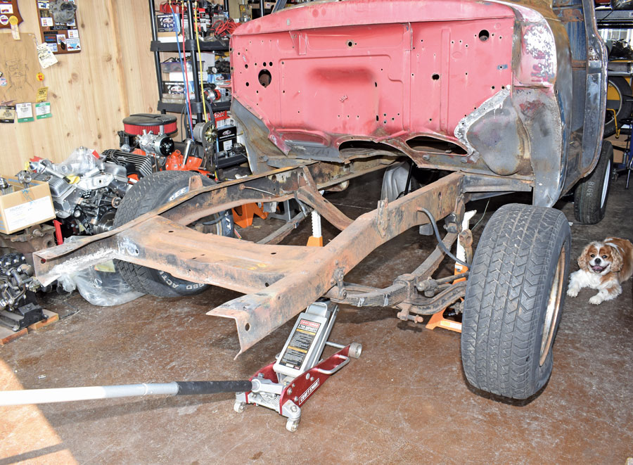
5. With our truck securely resting on jackstands, the stock front suspension and steering were removed while Scooter, the shop dog, looks on.
boxing plates tack-welded in place
5. With our truck securely resting on jackstands, the stock front suspension and steering were removed while Scooter, the shop dog, looks on.

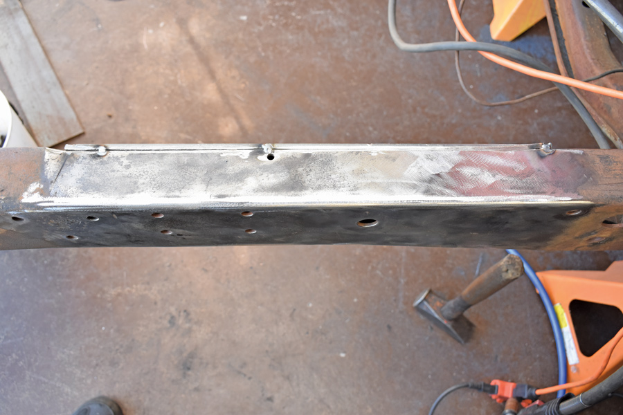
6. After removing the original shock mounts and cleaning the ’rails, the supplied boxing plates were tack-welded in place. We ground a V groove between the plates and the frame to ensure adequate weld penetration
6. After removing the original shock mounts and cleaning the ’rails, the supplied boxing plates were tack-welded in place. We ground a V groove between the plates and the frame to ensure adequate weld penetration
yellow markings on a stock axle
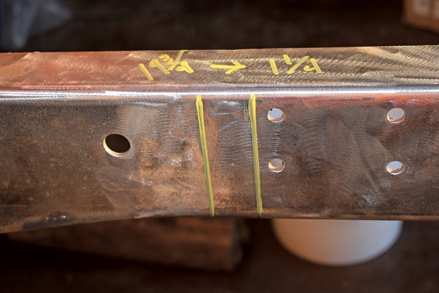
7. The stock axle centerline is 19 3/4 inches back from the center of the front shackle hole. We elected to move the wheels forward 1 1/4 inches.

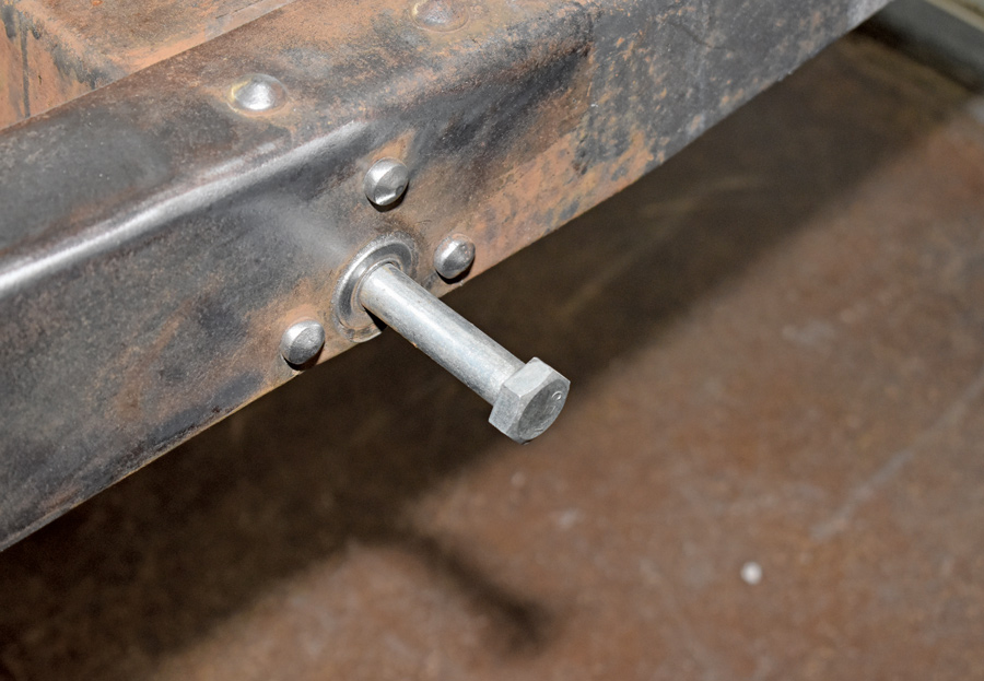
8. To simplify measuring we placed a 5/8-inch bolt in the shackle hole, then measured for the axle centerline by deducting half the bolt’s diameter, or 5/16 inch.
7. The stock axle centerline is 19 3/4 inches back from the center of the front shackle hole. We elected to move the wheels forward 1 1/4 inches.
5/8-inch bolt in the shackle hole
8. To simplify measuring we placed a 5/8-inch bolt in the shackle hole, then measured for the axle centerline by deducting half the bolt’s diameter, or 5/16 inch.
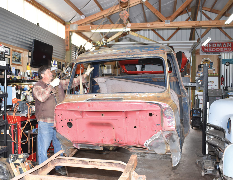
remove the cab so the frame could be flipped upside-down
9. We decided to remove the cab so the frame could be flipped upside-down to make welding easier. Paul Wilson learned if you drop by our shop you’ll be put to work.
upside-down frame
9. We decided to remove the cab so the frame could be flipped upside-down to make welding easier. Paul Wilson learned if you drop by our shop you’ll be put to work.

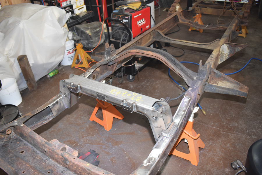
10. With the frame upside-down, the crossmember was positioned according to marks on the ‘rails and was welded in place.
10. With the frame upside-down, the crossmember was positioned according to marks on the ‘rails and was welded in place.
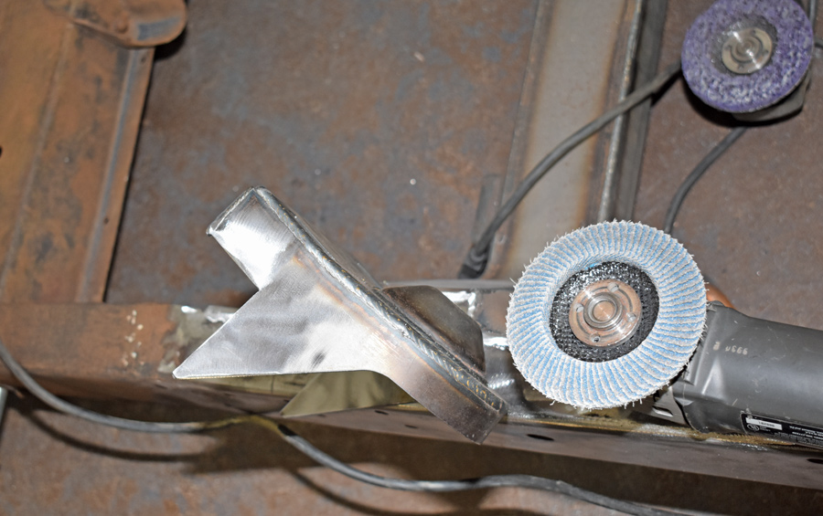
60-grit “flapper wheel” in use
11. Before any welding is done it’s a good idea to clean all the surfaces thoroughly. We found a 60-grit “flapper wheel” worked well.

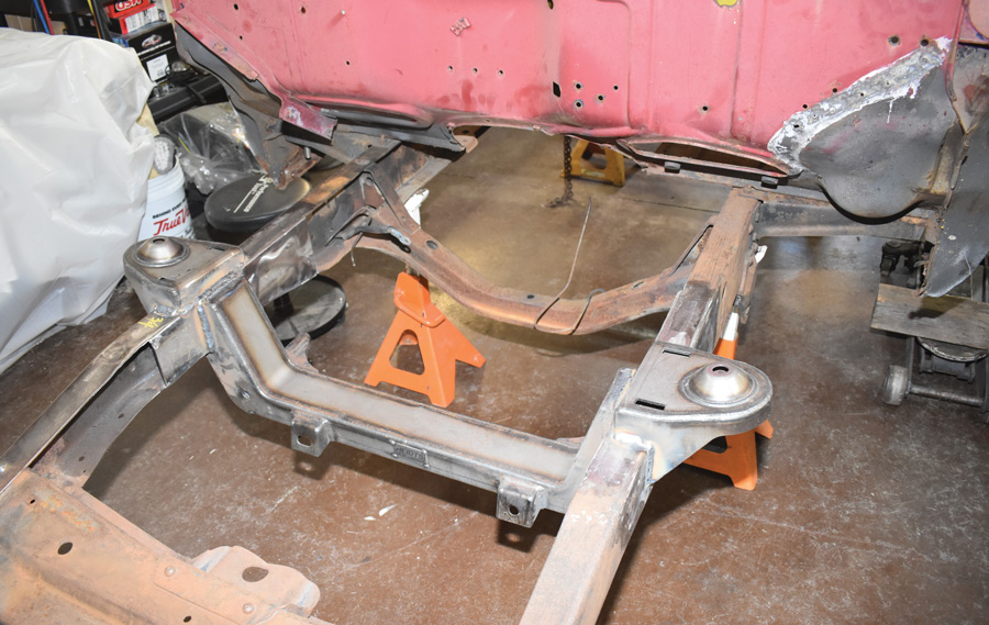
12. With the crossmember in place, next to be installed were the spring/upper A-arm towers. Note there is a left and a right (the tall side goes to the front of the chassis).

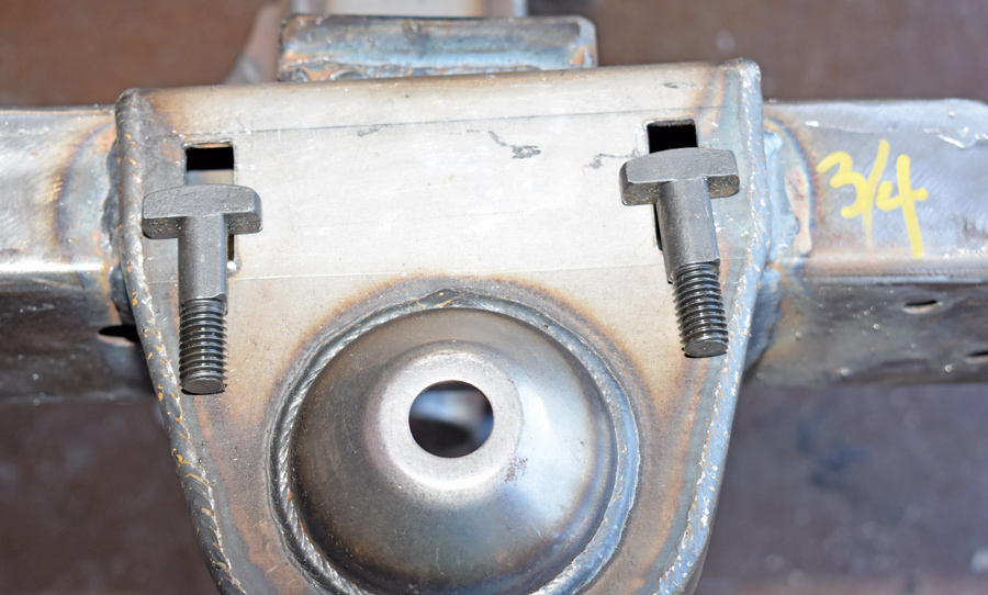
13. These are the T-bolts that anchor the upper cross shafts to the towers—the slots allow caster and camber to be adjusted. Note the T-bolts must be oriented 90 degrees to the length of the slots.
11. Before any welding is done it’s a good idea to clean all the surfaces thoroughly. We found a 60-grit “flapper wheel” worked well.
crossmember in place
12. With the crossmember in place, next to be installed were the spring/upper A-arm towers. Note there is a left and a right (the tall side goes to the front of the chassis).
t-bolts
13. These are the T-bolts that anchor the upper cross shafts to the towers—the slots allow caster and camber to be adjusted. Note the T-bolts must be oriented 90 degrees to the length of the slots.
One of the best known names in the suspension business today is Heidts, but like many of the giants in the aftermarket industry the company had a modest beginning. Gary Heidt started manufacturing parts in a 700-square-foot garage in 1985. How things have changed. Today Heidts occupies a 50,000-square-foot facility full of state-of-the-art equipment with production capacity that allows them to ship most orders within 24 hours.
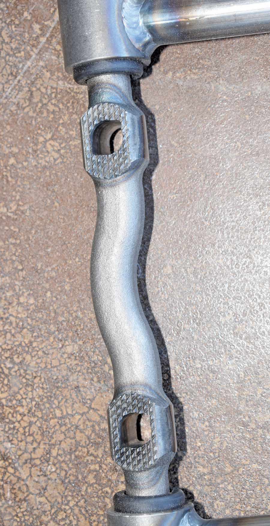
bottoms of the cross shafts
14. The bottoms of the cross shafts have serrations that bite into the towers and prevent the bolts from slipping. Avoid heavy coats of paint or powdercoating that could cause the cross shafts to slip and knock the frontend out of alignment.
Included in our Hcoil springs and shock absorbers
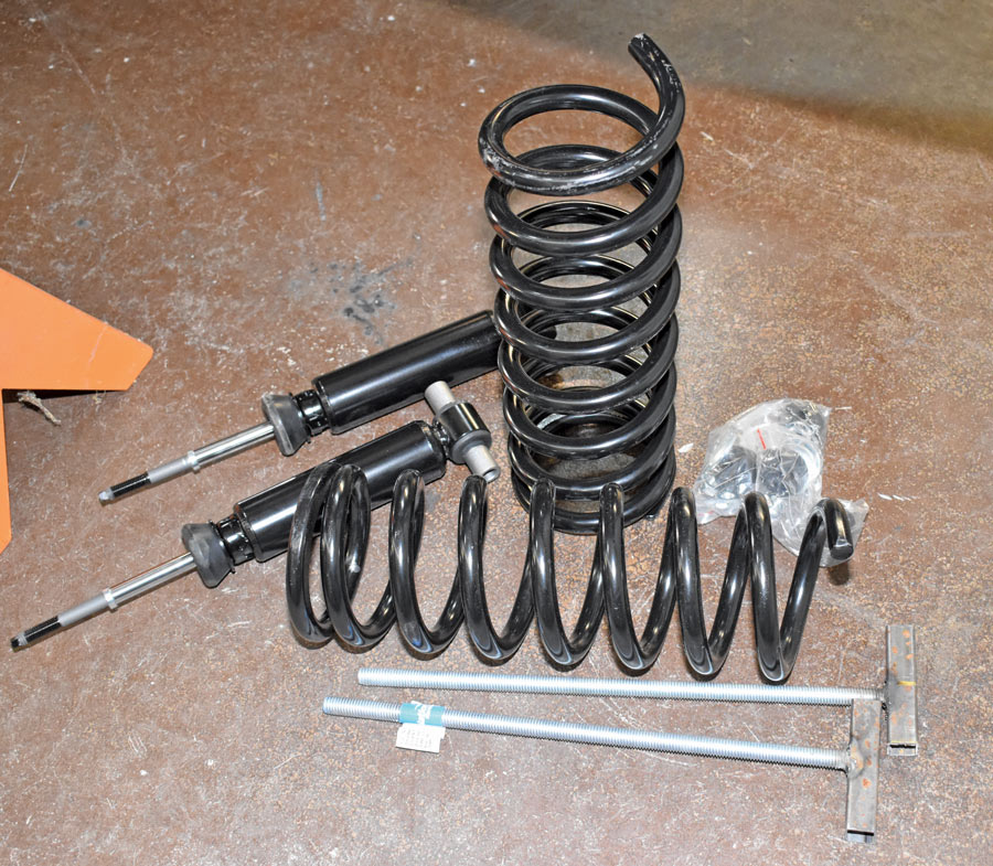
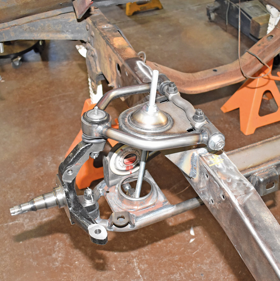
15. Included in our Heidts kit were coil springs and shock absorbers. As we would not be installing them at this point, we made temporary struts from threaded rod and tubing
close up of a spring
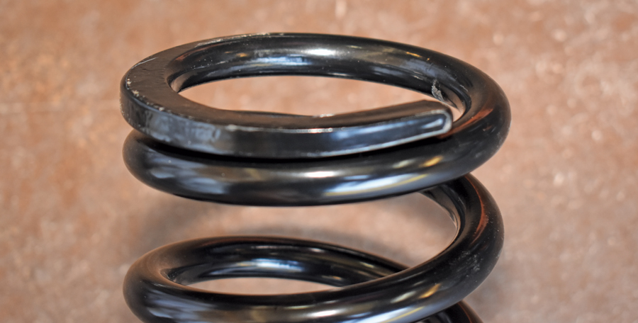
16. The springs have a top and a bottom. The “pigtails” visible in the previous photo fit into depressions in the lower A-arms. The tops of the coils are ground flat to seat in the upper brackets.
14. The bottoms of the cross shafts have serrations that bite into the towers and prevent the bolts from slipping. Avoid heavy coats of paint or powdercoating that could cause the cross shafts to slip and knock the frontend out of alignment.

15. Included in our Heidts kit were coil springs and shock absorbers. As we would not be installing them at this point, we made temporary struts from threaded rod and tubing

16. The springs have a top and a bottom. The “pigtails” visible in the previous photo fit into depressions in the lower A-arms. The tops of the coils are ground flat to seat in the upper brackets.

temporary struts installed
17. With the temporary struts installed we adjusted them until the lower A-arms were level with the ground.
With the stock steering and suspension removed, the first steps in our truck’s transformation were to place it on jackstands and then level it side-to-side with the front of the frame slightly lower than the rear (approximately a 2 1/2-degree rake). Following Heidts’ instructions we measured back from the center of the front shackle holes 19 3/4 inches and made a mark (check the photos for a little trick to make this easier). This would be the center line of the front wheels and crossmember.

While Heidts’ location of the front crossmember puts the wheels in the original location, 1953-1956 Ford pickups have a slight peculiarity in this regard. In stock form the front wheels are slightly to the rear in the fender openings. Some sticklers for accuracy prefer them that way, however we elected to move the crossmember forward 1 1/4 inches to move the tires closer to the front of the fenderwell. With the crossmember located and centered side to side it was welded in place. The next step was the installation of the spring towers. Be aware there is a left and right—the built-in angle in the towers provides antidive geometry that keeps the nose of the truck from diving under braking.

Installing the control arms and spindles is straight forward but in our case we elected not to install the coil springs and shocks just yet. As the engine and transmission have yet to be installed, the coil springs would not only be difficult to compress due to the lack of weight on them but the shocks could possibly be damaged by prolonged overextension (especially bouncing up and down on a trailer on its way home). To hold the suspension at the proper ride height we fabricated a pair of struts from threaded rod and tubing.
caliper brackets
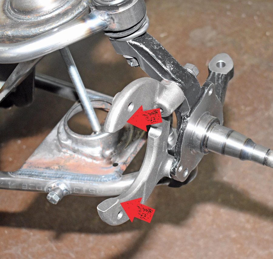
18. The caliper brackets attach to the spindles with two bolts. There are two flat surfaces (arrows) that the calipers slide on. They should receive a light coat of lubricant.
11-inch rotors in place
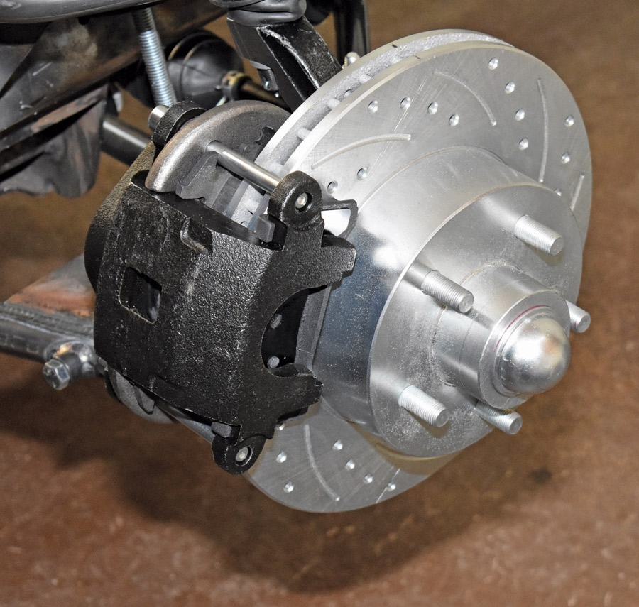
19. Here the 11-inch rotors are in place. Note the direction to the slots and holes—the outer ends of both should point toward the rear of the chassis.
GM calipers
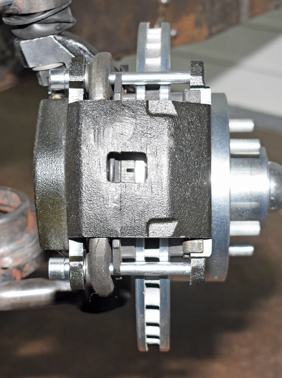
20. The GM calipers are secured by two pins (along with those flat surfaces on the mounting brackets) that allow the caliper to slide in operation and as the pads wear.
18. The caliper brackets attach to the spindles with two bolts. There are two flat surfaces (arrows) that the calipers slide on. They should receive a light coat of lubricant.

19. Here the 11-inch rotors are in place. Note the direction to the slots and holes—the outer ends of both should point toward the rear of the chassis.

20. The GM calipers are secured by two pins (along with those flat surfaces on the mounting brackets) that allow the caliper to slide in operation and as the pads wear.

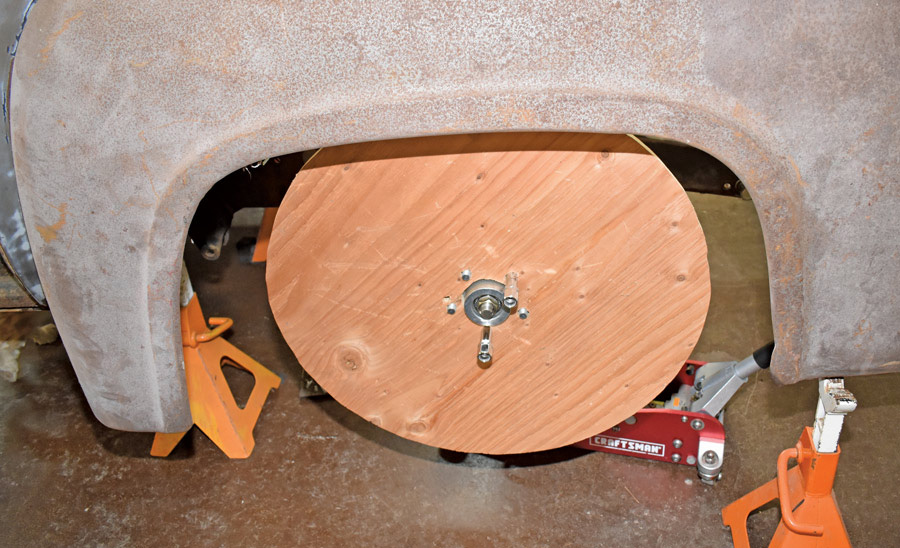
21. Before we did all the final welding we mocked up the front fender with a wood wheel the same diameter as the tires that will be used. This is with the wheels moved forward 1 1/4 inches.
mock up wood wheel
21. Before we did all the final welding we mocked up the front fender with a wood wheel the same diameter as the tires that will be used. This is with the wheels moved forward 1 1/4 inches.
22. This is the inner tie-rod end on the rack-and-pinion steering. Due to the tread width difference between a Mustang II and an F-100, these pivot points have to be widened to prevent bumpsteer.
car part and bottle of glue
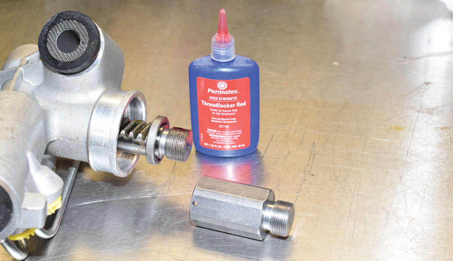
23. Heidts supplied these extensions that thread onto the rack. They’re installed with high-strength thread locker and secured with roll pins (note the hole in the extender).
24. With the spindles roughly aligned, the widened rack was centered in its travel and then bolted in place. The last part to be put in place was antiroll bar.
widened rack
24. With the spindles roughly aligned, the widened rack was centered in its travel and then bolted in place. The last part to be put in place was antiroll bar.
If the Mustang II front suspension had a shortcoming it was the 9 1/4-inch-diameter brake rotors and small-bore calipers. For beefier brakes we can count on, we used 11-inch drilled-and-slotted rotors, GM calipers, and custom brackets to attach them to the Mustang II–style spindle. One last step in our IFS installation was the addition of 2-inch extensions on each side of the steering rack, as F-100s have a 4-inch-wider track than a Mustang II.

With the new suspension system in place, the first trip the truck will make under its own power will be to an alignment shop. Alignment specifications are: caster 1 degree positive, camber 1/2 degree positive, toe 1/8 plus or minus. Then it will be time to forget the buggy suspension and enjoy all the benefits an IFS with disc brakes and power rack-and-pinion steering have to offer.

 SOURCES

Heidts Hot Rod & Muscle Car Parts
(800) 841-8188
www.heidts.com

Speedway Motors
(800) 979-0122
www.speedwaymotors.com