CTP Tech
InTheGarageMedia.com
"Independent Thinking"
1. This is the first series ’55 Chevrolet pickup frame that will be the foundation of a ’52 pickup. So far we’ve made it square, installed the Flat Out Engineering front crossmember for Corvette IFS, and added a Progressive Automotive center crossmember.
Part 1: C4 Corvette Suspension for Early Chevy Pickups: Squaring Things Up
BY Ron CeridonoPhotography BY the Author
L

ike most manufacturers, as World War II came to a close, Chevrolet resumed production of cars and trucks with what were essentially prewar designs. Chevy’s AK series was introduced in 1941, continued in 1942, but wasn’t available to civilians again until 1946 (from 1943-45 GM continued to build trucks for the military).

In 1947 Chevrolet introduced what is arguably one of their best styling efforts, the new Advance Design series trucks with what was called the Unisteel cab. The series remained in production with minor alterations through 1953. In 1954, some noticeable changes occurred, including a one-piece windshield and a new grille. For the first part of 1955, other than some new emblems and the elimination of the torque tube driveline, not much changed until the all-new Task Force series was introduced. As a result, these trucks are usually referred to as the ’54/first series ’55 style while second series is used to describe new ’55 design.

Advanced Design pickups are a hot commodity and Paul Wilson was fortunate enough to come across the near-perfect ’52 Chevy truck cab and front sheetmetal; unfortunately the frame was beyond saving. As luck would have it, a ’54/first series ’55 frame was found and the price was right but there were still issues to resolve, which we will explain.

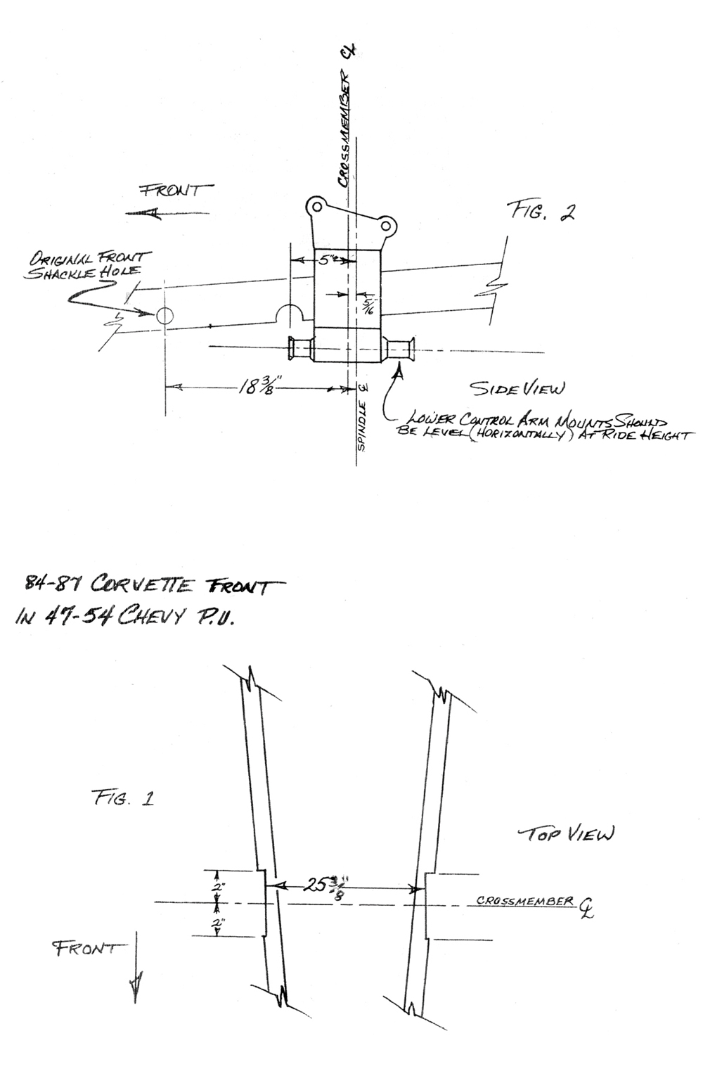
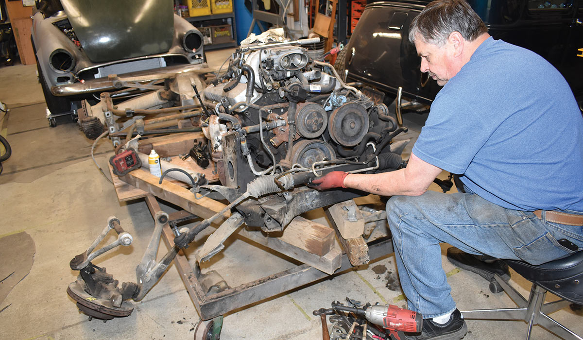
To update his truck Wilson decided to install C4 Corvette front and rear independent suspension with components from Don McNeil’s Flat Out Engineering. McNeil is a true hot rod pioneer who has been involved as a drag racer, Bonneville competitor, award-winning car and truck builder, as well as a businessman. Today McNeil specializes in kits to install ’84-96 Corvette C4 front and rear suspension components under an array of Chevy and Ford cars and trucks. These kits maintain the correct geometry and handling characteristics C4 Corvettes are known for and are designed to be easy to install. They come with all the hardware required and detailed instructions.

Like the Advance Design Chevy pickups there were two versions of the C4 Corvette suspension systems. McNeil tells us the ’84-87 Corvette front suspensions are approximately 1 inch narrower at 61 inches than the ’88-96 versions; ’84-87 front suspensions have 11-inch front brake rotors, so most 15-inch will fit; ’88-96 front suspensions have 12-inch front rotors so 16-inch or larger wheels must be used. In the rear, ’84-87 suspensions are  61-1/2 inches wide, wheel flange to wheel flange, and used parking brakes inside the rotor hats. The ’88-96 is 1-inch wider at 62-1/2 inches and the parking brakes are built into the caliper. Both series use the 5-on-4.75 wheel bolt pattern, forged aluminum spindle uprights, A-arms, half shafts, and control arms that are not only lightweight but incredibly strong. These lightweight aluminum components give the suspension system a sprung to unsprung weight ratio that is unsurpassed.

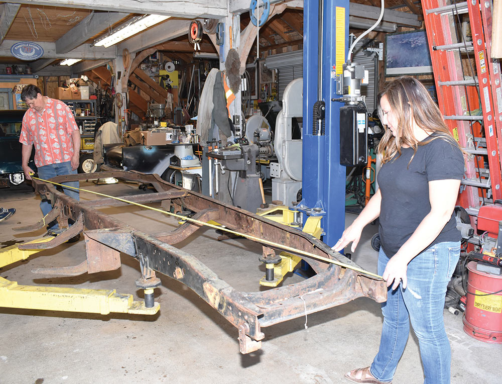
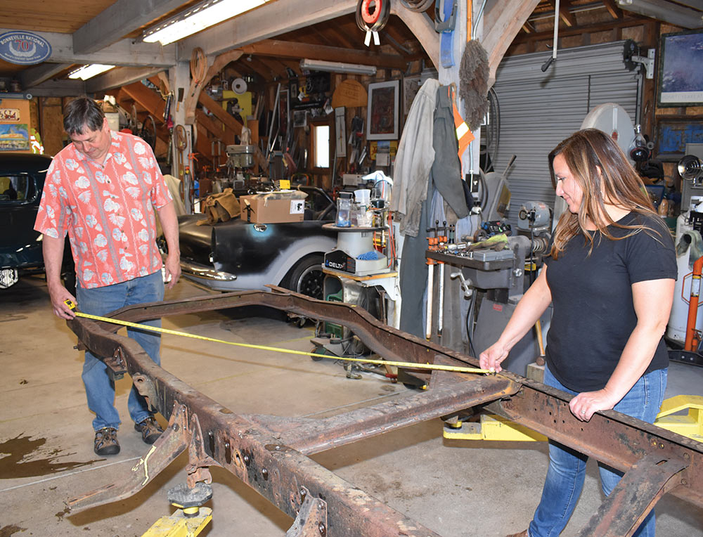
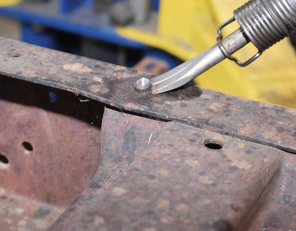
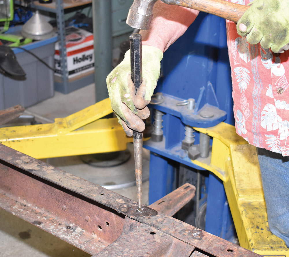
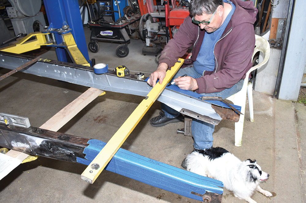
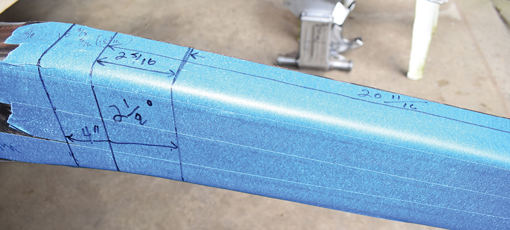
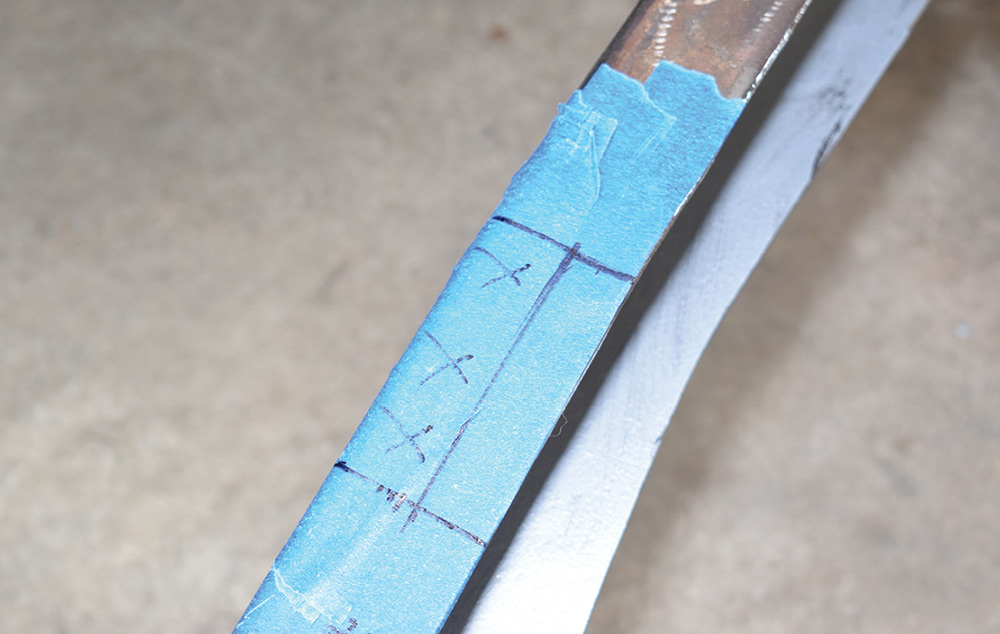
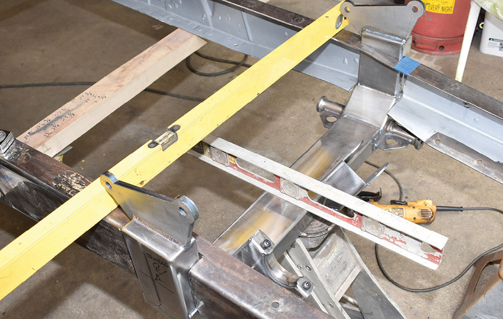
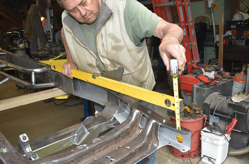
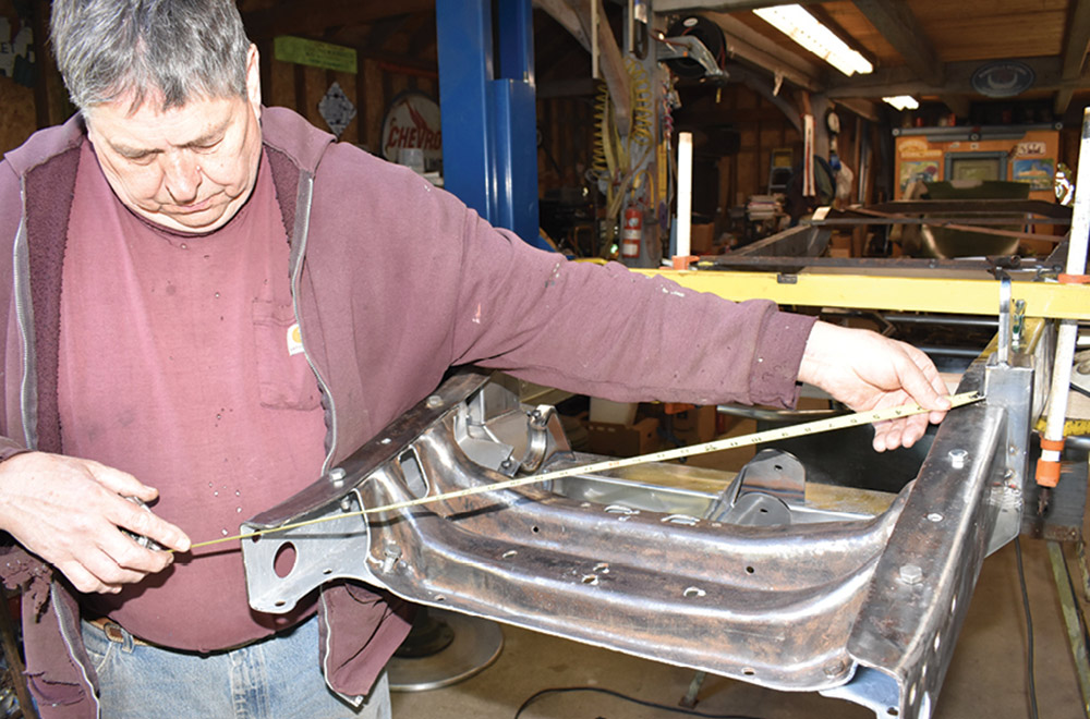
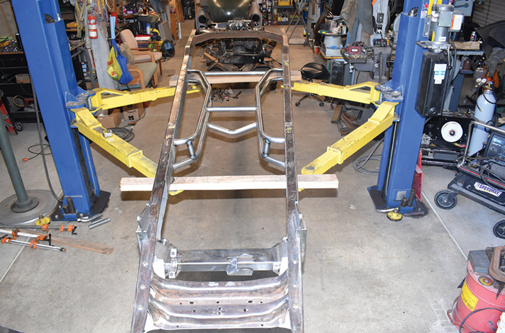
A critical part of installing any suspension component is making sure the frame is a solid foundation to build on—ours was not. When cross measuring our frame (from left front to right rear and right front to left rear) we found it was 5/16 out of square—1/16 is considered to be the maximum deviation. The frame showed no sign of damage so we assumed it left the factory that way, but regardless of the cause it had to be fixed.

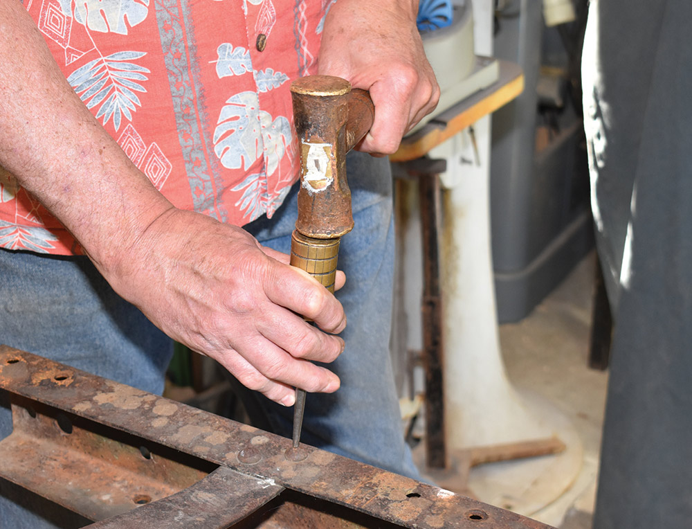
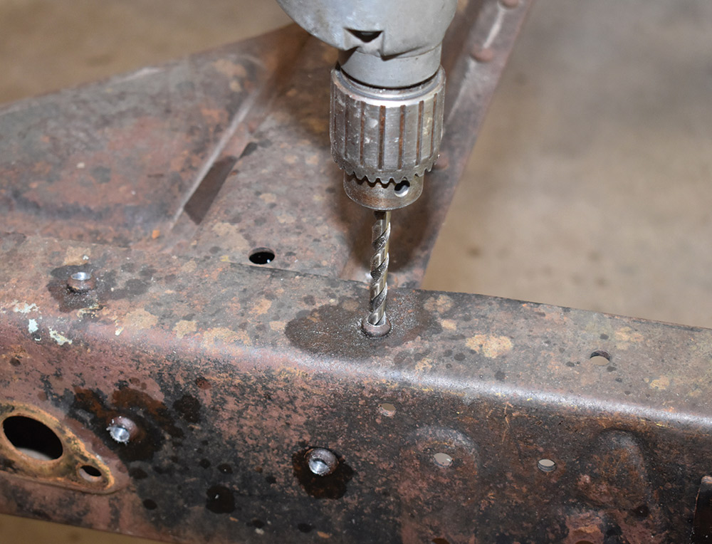
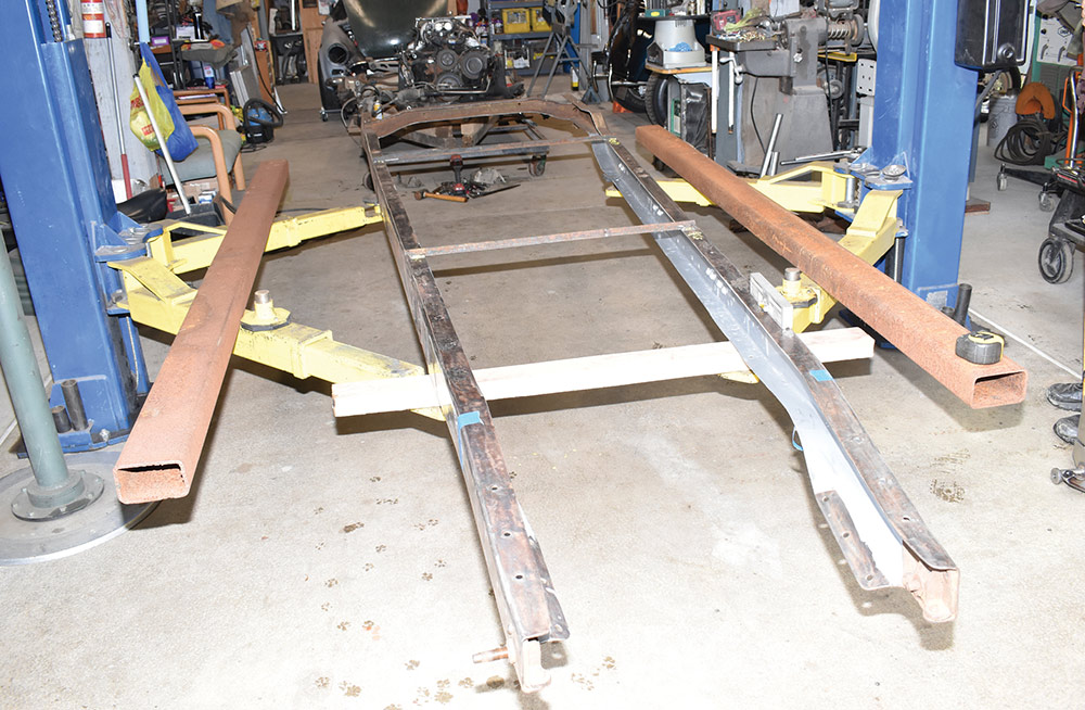
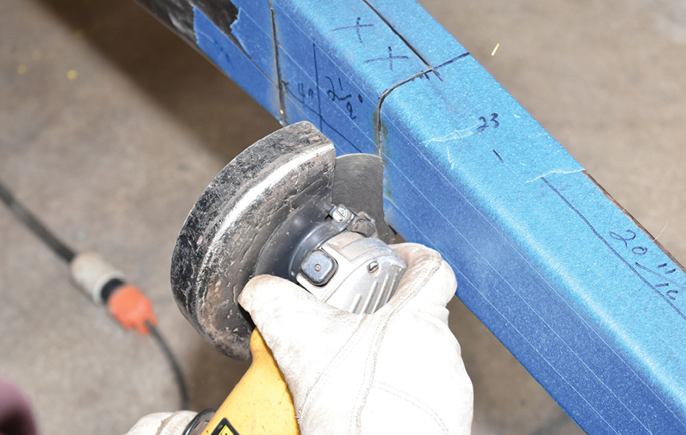
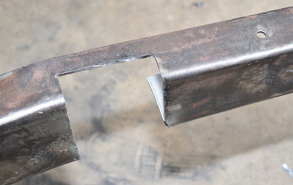
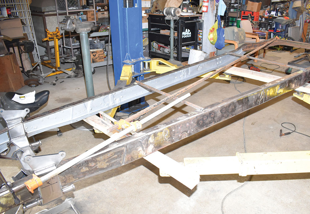
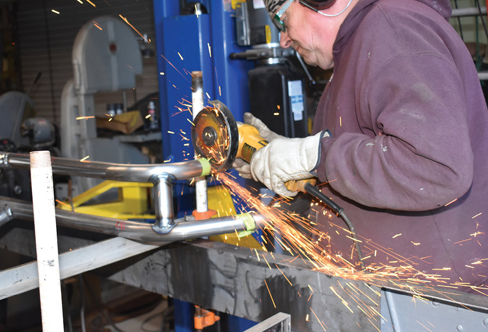
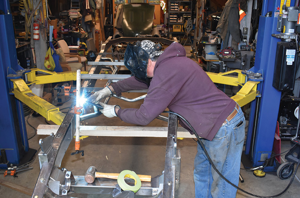
To resolve the problem with the frame we removed all but the very rear crossmembers as it wouldn’t budge with them in place. Removing the crossmembers did two things, it made the frame limber enough to make it square. It also made it possible to push the front of the framerails together, put the Flat Out crossmember in place then spread the frame apart so the notches that were previously cut fit around the uprights of the C4 crossmember without cutting off the framehorns. Once square the original crossmembers were replaced by an X-member from Progressive Automotive. All things considered, particularly with a frame that is square with the stock crossmembers, remain in place, it would be quicker and easier to cut off the framehorns as the Flat Out instructions show.

Next time around we’ll show how to rebuild and install the front suspension components followed by installing the C4 IRS. It’s all part of our independent thinking.

Paul Wilson and Merissa Ceridono cross measuring the frame
2. Paul Wilson and Merissa Ceridono cross measured the Chevy’s frame and found it to be 5/16 inch out of square—that would have to be addressed before going any further.
Cross measuring between crossmembers
3. The frame was measured diagonally from end to end. In between all the crossmembers the results weren’t encouraging, but at least they were consistent.
Centerpunching crossmember rivets
4. To square the frame it would be necessary to remove the crossmembers. That process began by centerpunching the heads of all the rivets holding the crossmembers in place.
Drilling out the rivets
5. The heads of the rivets were then drilled. Before the crossmembers were removed angle iron braces were welded to the rails to prevent them from spreading apart.
Knocking out rivets with air chisel
6. After the heads of the rivets were drilled an air chisel was used to knock them off.
Punching out remains of rivets
7. With the heads of the rivets removed the remaining portions were knocked out with a punch.
Clamping framerails to hoist
8. Our original plan was to place the framerails on lengths of rectangular tubing but decided against it. Instead we clamped the rails to the legs of the hoist.
Leveling framerails
9. Using washers as shims on the hoist arms the framerails were leveled side to side and set at a 2-1/2-degree angle to simulate the truck’s nose down rake at ride height.
Diagrams and instructions for crossmember positioning
10. Flat Out Engineering’s instructions for positioning the front crossmember are easy to follow. Note the precaution that the lower control arm mounts should be level.
Taped framerails
11. We taped the framerails so our layout lines would be easy to see. Here Wilson establishes the spindle centerline on each side while Buddy the wonder dog guards the door.
Drawn layout lines on taped rails
12. Notches have to be cut in the framerails to accommodate the Flat Out front crossmember. They were laid out to tilt the crossmember back 2-1/2 degrees to keep the control arms level.
Taped section marked for removal
13. When the notches were cut the portions with the Xs were removed, leaving small strips of the ’rails intact.
Cutting notches in frame with abrasive wheel
14. The 4-inch-wide notches in the framerails were carefully cut with an abrasive wheel. The goal is to make a tight fit between the crossmember and the ’rails.
Notched section of framerail
15. This is the completed cut on the passenger side framerail—we didn’t cut the framehorns off for the reasons outlined in the text.
Sketch of framerail and new crossmember installation
16. In normal circumstances cutting off the front of the frame with the stock crossmember left in place is the easiest way to install the Flat Out crossmember. Our circumstances weren’t normal.
Positioning new crossmember before welding
17. With the frame verified as level side to side and nose down 2-1/2 degrees the new crossmember was positioned and tack welded in place.
Using pipe clamps to square the frame
18. To pull the frame into square we used a pair of pipe clamps. Once squared additional diagonal angle iron braces were then added to hold the framerails in place.
Welding x-member
19. Rather than reinstall the original crossmembers we opted to install a tubing X-member from Progressive Automotive. Prior to installation the framerails were boxed.
X-member mocked up in position
20. The Progressive Automotive X-member is a universal design that has to be trimmed to fit. The frame may be boxed just where the X-member attaches to the frame, or as we did the entire length of the ’rails.
Trimming X-member with wheel
21. With the X-member centered in the frame and located the proper distance from the front spindle centerline it was trimmed to fit.
Tack welding X-member in place
22. The framerails were once again checked to ensure they were level and square, then the X-member was tacked in place. All dimensions were checked again before the final welding was done.
Measuring drop of framehorns
23. Before the final welding was done on the Flat Out crossmember, the drop of the framehorns was checked to ensure it was 3-1/8 inches from the top of the framerails.
Final measurement on framehorns
24. A final measurement was made to make sure the framehorns were square. Once that was confirmed, the new C4 crossmember was welded in place.
Squared frame with X-member and crossmember installed
25. At this point the frame is square, the X-member is in place, and the Flat Out crossmember is installed.
Preparing donor '86 Corvette suspension assemblies
26. The next chore is to clean and rebuild the front and rear suspension from the donor ’86 Corvette.
 SOURCES
Flat Out Engineering
(714) 639-2623
flatout-engineering.com
Progressive Automotive
progressiveautomotive.com