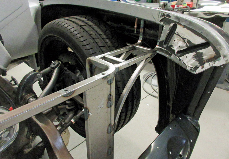
Tech
InTheGarageMedia.com

1. A sturdy support is needed to cradle the radiator core and tie the tops of the front fenders together. This support is made of square tubing with some flat reinforcing plates.

The Souza F-100
Crafting a Custom Aluminum Fan Shroud

BY Ron CovellPhotography BY The Author
T

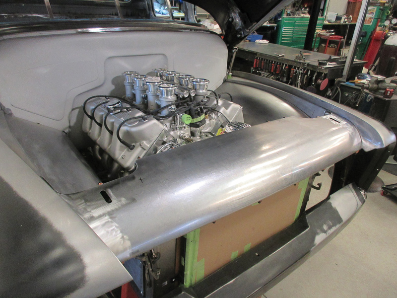
he most recent project to be completed on the Souza F-100 is the fan shroud. This is actually several panels carefully crafted to fit cleanly together, which not only ensures that the fans draw air efficiently through the radiator but that they also continue the smooth, sweeping curves that encircle the engine, adding a lot of style and showcasing the powerplant when the hood is open. These panels involve some tricky layout and fitting, and you may very well pick up some good tips that can help with other projects.

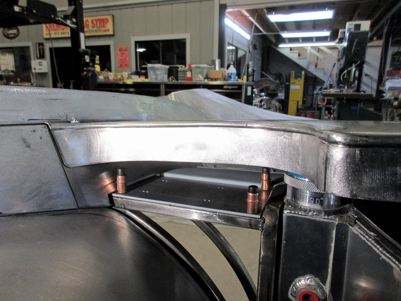
Of course the radiator has to be located and securely mounted before any of this work can begin. The team at Gary’s Rods & Restorations built a sturdy core support from square steel tubing and plates were added to this structure to securely cradle the radiator. With the radiator in place, the fitting of the panels was started.

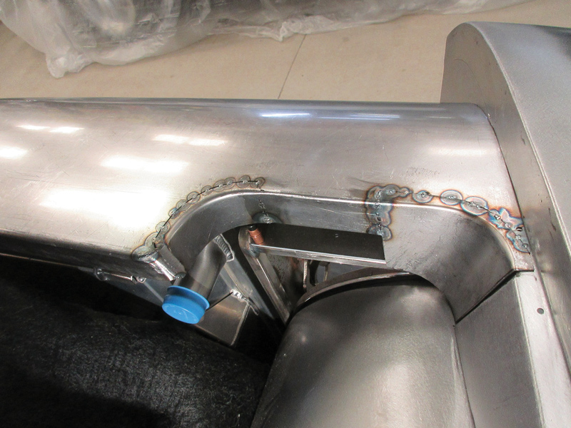
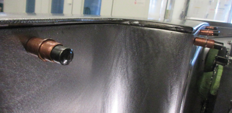
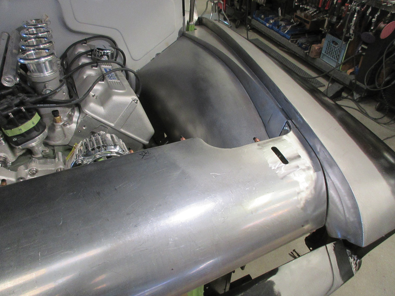
The first panel to be fabricated is a curved header that covers the top of the radiator and spans the entire distance between the front fenders. This panel was given a gentle arch toward the center, in keeping with the beautifully contoured inner fender panels covered in the last article.

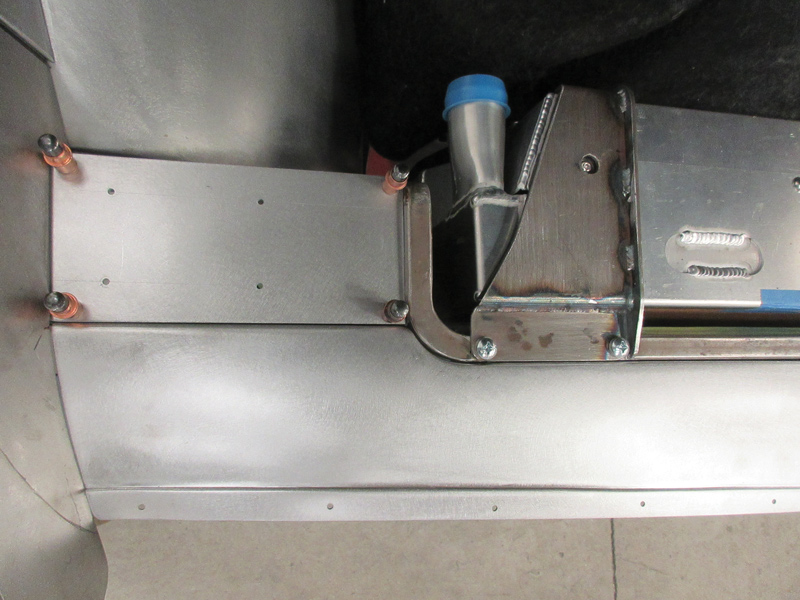
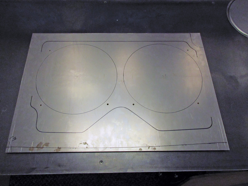
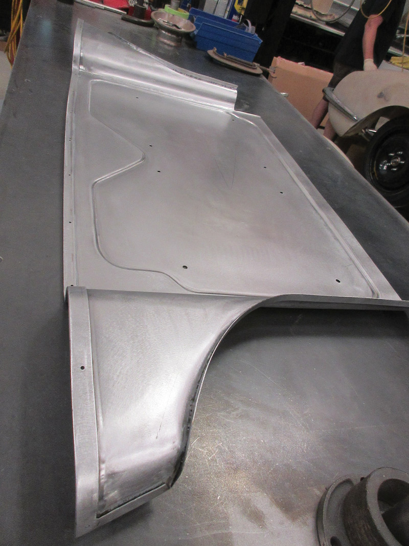
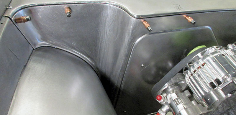
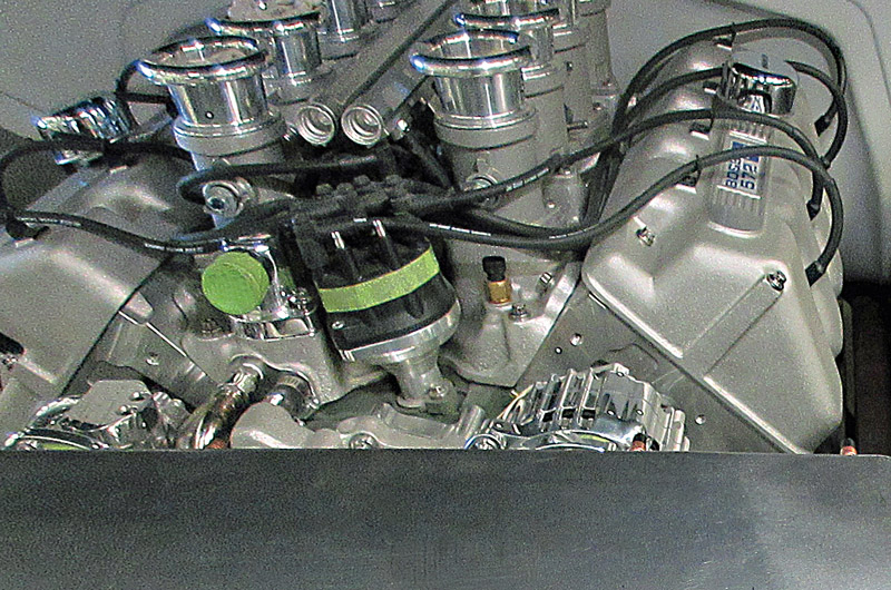
Once this panel was shaped, trimmed, and fitted, a large panel was designed to fit close to the twin fans, which are controlled by the engine management ECU. A decision was made to put a stepped detail in this panel, which gives it more strength and becomes a strong design element.

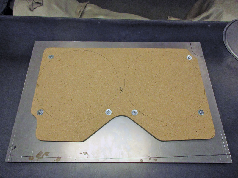
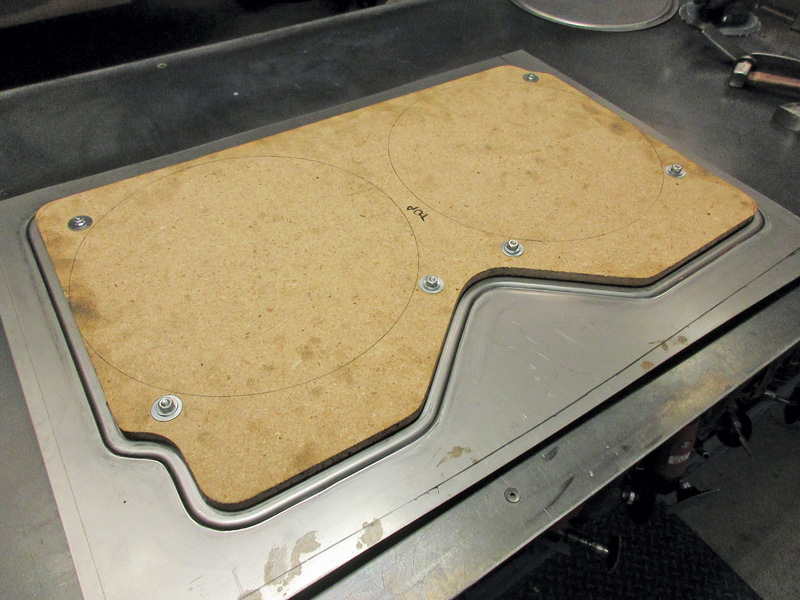
A pattern was made from 3/4-inch MDF to guide the panel through a Pullmax machine, outfitted with a set of rounded step dies. As you’ll see in the photos, this really gives the panel a finished and professional appearance.

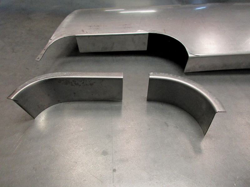
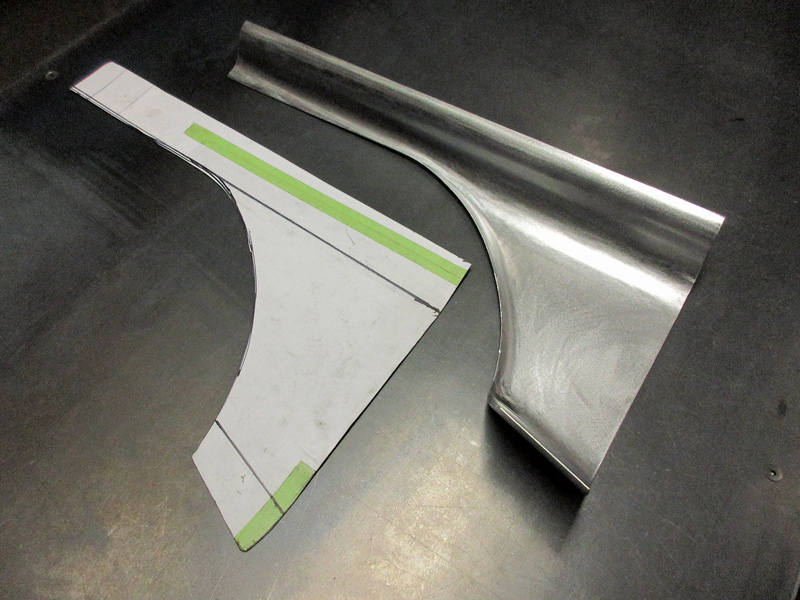
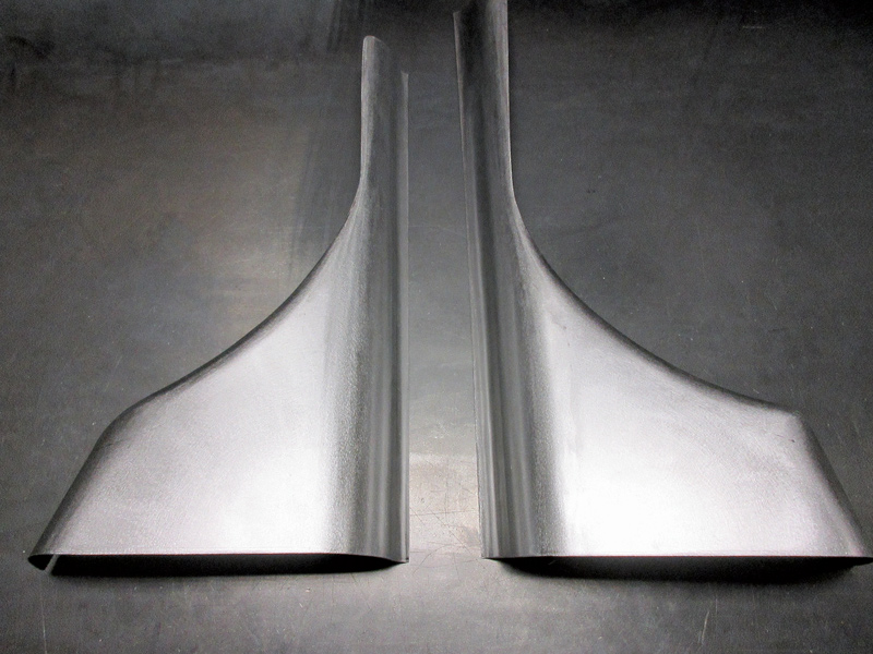
With the center portion roughed out, the next step was to fit the very convoluted side pieces, which have to fit snugly on all edges. These were patterned with chip board, then carefully trimmed and fitted with precision. Anyone who has attempted making a convoluted panel like this will appreciate what it takes to get a snug fit.

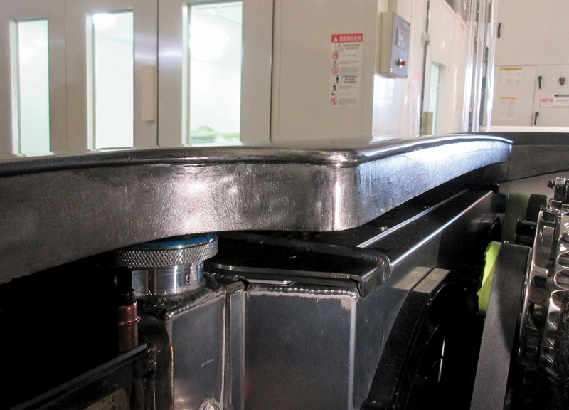
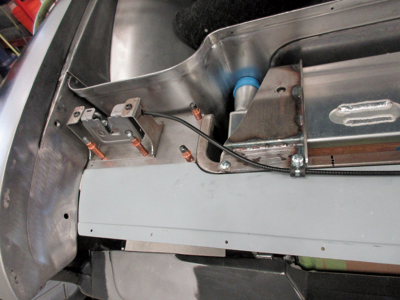
With the three rear panels shaped, fitted, and joined together, a step was made on the rear flange on the header panel so the reinforced edges of the rear panels would fit flush. This step was made with a beading machine, and as you can see it adds an attractive detail to the joint.

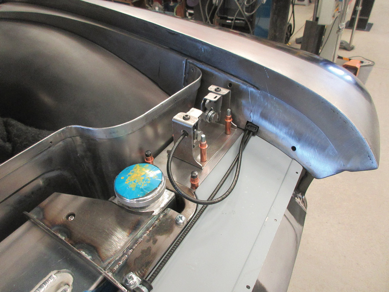
There were a few more steps involved to bring this project to completion, which you’ll see in the photos. Look for more articles on the Souza F-100 in the months to come.

close up of welds
2. Note how all the corners of the core support have been carefully rounded, adding an element of style to the construction.
sheetmetal structure
3. The tubular core support provides a beefy structure for the radiator mounts and the sheetmetal that ducts all the air through the radiator.
top header panel before welded
4. The top header panel was next to be fabricated. It spans the distance between the front fenders and has a gentle arch in the center. The radiused pockets on each side were accomplished by fitting two curved angles into place.
welds on top header panel
5. Here you can see the filler pieces tack-welded into place. Great care was taken to place all welds away from the corners to ensure a uniform radius in those areas.
layout of sheet metal<br />
6. This is the layout for the fan location, showing the reinforcing step on the perimeter of the panel.
pattern made on 3/4 inch MDF
7. A pattern was made from 3/4-inch MDF to guide the panel through the Pullmax machine to make a uniform step.
8. Here is the step, fresh off the Pullmax machine.
chip board pattern made with sheet metal
9. A chip board pattern was made for the panels that fit next to the center panel. One metal piece has been made from the pattern and rough-shaped.
panels side by side
10. The matching panel for the other side of the engine compartment is shaped here.
all 3 panels welded together
11. Here all three of the panels have been welded together. Note that the top edge has been reinforced by welding an additional strip of metal to it.
close up of flange
12. To enable the double-thickness panel to fit flush, a beading machine was used to form a recess on the top flange.
another close up
13. This close-up shot shows how uniform the stepped-down area is where it wraps around the concave area. As you can see, everything is fitted beautifully.
14. Here you can see how nicely the panels fit together, with a snug, uniform gap. As with everything else on this truck, the craftsmanship is impeccable.
assembly coming together
15. It takes a lot of careful fitting to keep the gaps uniform around a contoured recess like this. The openings for the fans will be cut at a later stage.
bmw latches
16. Latches from a BMW are used, and special mounts were made to hold them securely in the proper location.
another view of the BMW latches
17. Both latches are cable-operated with the original BMW cables.
openings that were made
18. Small openings were made in the header panel for the latch strikers to enter, presenting a very clean look with the hood open.
custom overflow
19. A custom-fabricated coolant overflow tank will be mounted directly to the thermostat housing. This will hide the distributor and wires, presenting a very clean appearance.
assembly completed, everything welded and bolted together
20. Here’s an overview of all the underhood sheetmetal fabrication–truly an exquisite display of craftsmanship.
Gary’s Rods & Restorations
(831) 728-7025
garysrods.com