 Tech
Tech
InTheGarageMedia.com


 PHOTOGRAPHY BY Camren Beattie
an, you’re really putting me on the spot this month! My favorite parts of the truck so far, that we haven’t covered, have to be the engine bay and headers. The engine bay is just so completely off the wall for a truck like that, but I think that’s what makes it so cool. It’s also one of those things where I just did what I thought could be cool since we had no rendering or guideline at all for the engine bay.
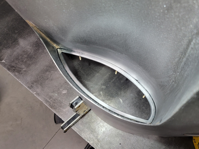
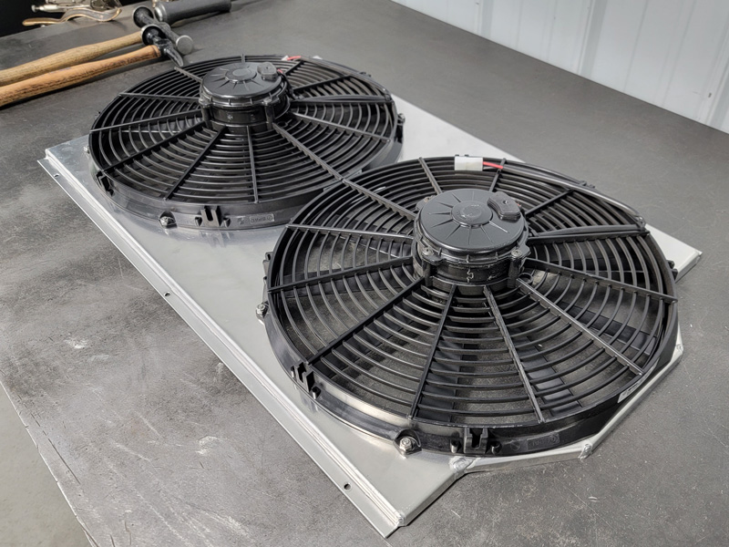
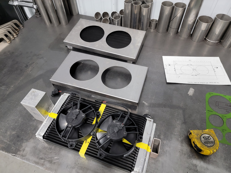
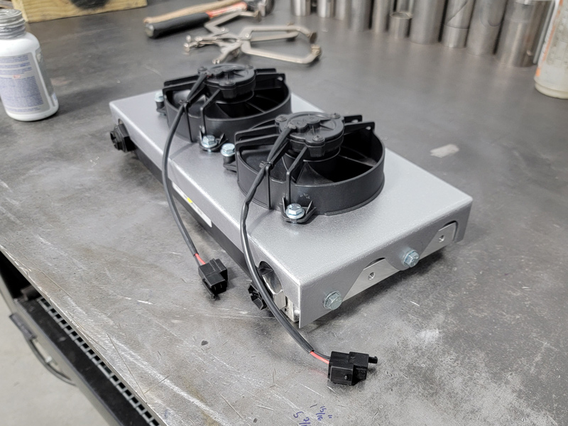
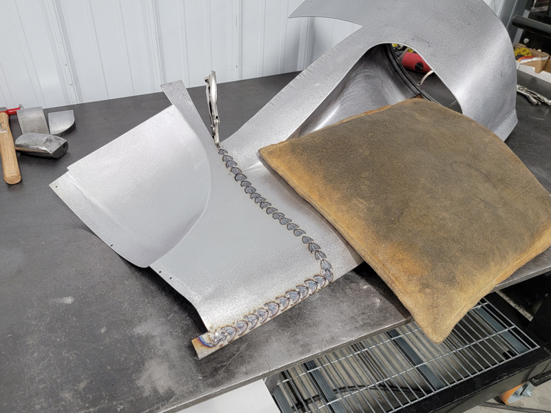
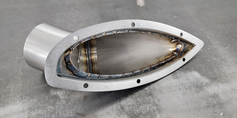
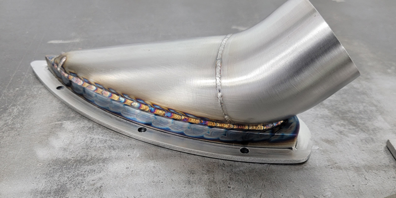
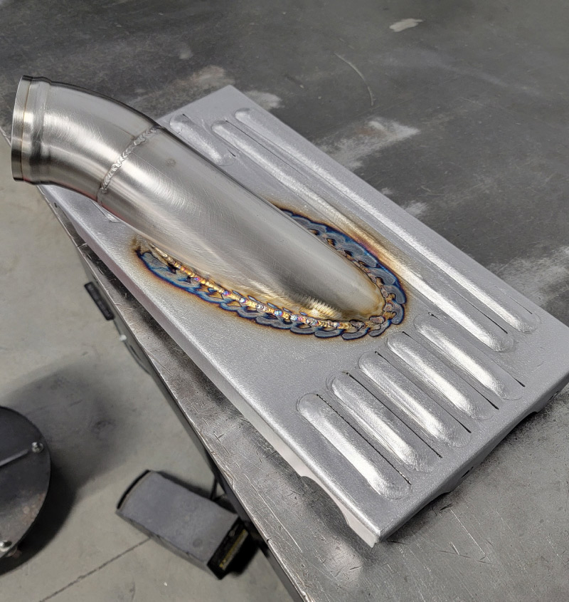
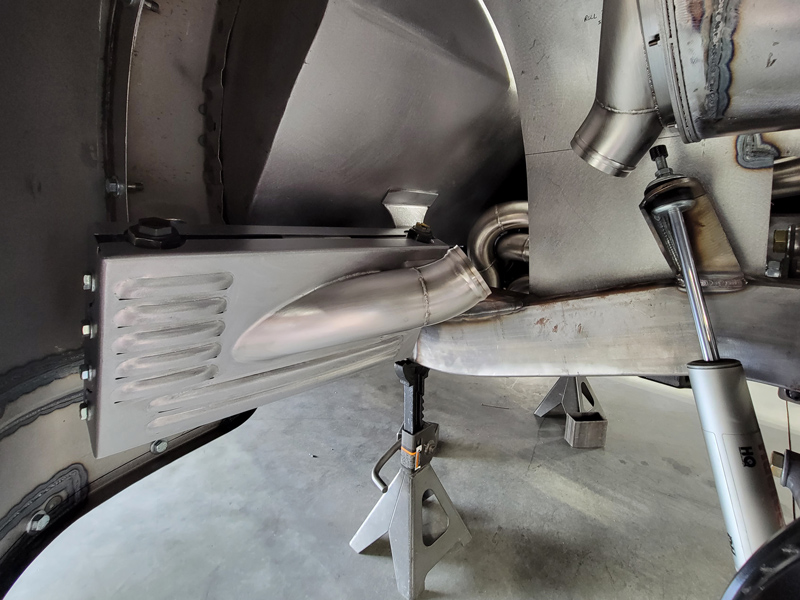
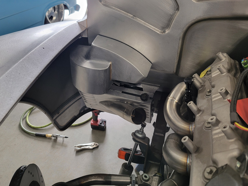
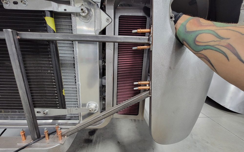
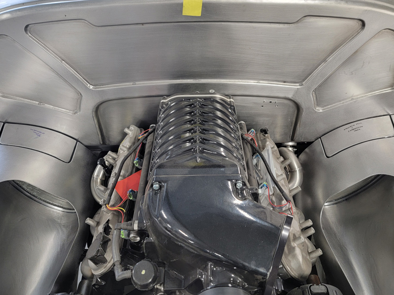
When it came time to do the engine bay for Brian’s truck, I had one clear thought: Get fresh air in and get hot air out. With 1,076 hp and 980 lb-ft of torque, that Whipple supercharged LS3 from Wegner Automotive had to stay cool and breathe. Knowing that we had to make that happen, we had PRC give us a radiator with the largest core they could provide that we could possibly fit in the truck with dual electric fans. There wasn’t much room to put a good size heat exchanger in front of it with how close the grille bars would end up mounting to it, so I had to get creative and come up with another location for one. I ended up figuring out that I could just barely fit a decent size heat exchanger behind each front wheel with dual electric fans. Knowing where those were going to be located, I started building the passenger inner fender, but was trying to figure out how to get air down to those heat exchangers. I ended up taking a little bit of inspiration from one of Brian’s other cars he has in his garage—his Lamborghini Aventador. It has a ton of air vents and ducts to cool down various parts throughout the car, and I thought that would be awesome if I could try and do something similar. Never having made a “scoop” or air vent before, it was a bit of a learning curve initially trying to figure out how to build and shape it all, and it became even more interesting when trying to shape it into the surrounding inner fender. With that figured out, I switched over to the driver side and got that inner fender built/caught up with the passenger so I could move onto the next set of panels for the engine bay. I ended up making a new fan shroud that would flow better with the engine bay and started working on the radiator closeout panels that would mount to the fan shroud at the front and to the inner fender at the rear. These panels were really interesting to figure out since the fans/fan shroud were wider than the opening of the engine bay from the top of the fenders. Luckily, there was enough room to make these surrounds, even with the suspension fully compressed and turned lock/lock. With those panels made, I got all the parts in to make the heat exchanger fan shrouds, rock guards, and mounts. I built the fan shrouds and rock guards out of 16g and put mesh behind the rock guard and louvered them to gain some extra airflow and protection from road debris. From there, I thought it would be cool if I could run ducting from the vents in the inner fenders to the heat exchangers, effectively making them air dams. I built some trim rings for the vent openings and sandwiched mesh between them for a little extra protection and flare and used 3-inch stainless pipe to direct that air down into the heat exchangers. We plan on using some high-performance ducting to connect the two pipes since it’ll handle the abuse being under the fender but will be flexible and easy enough to remove and install.
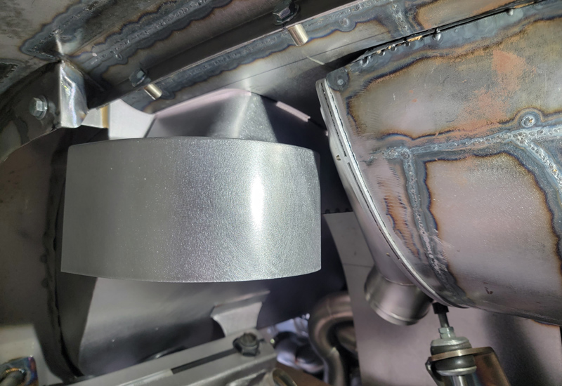
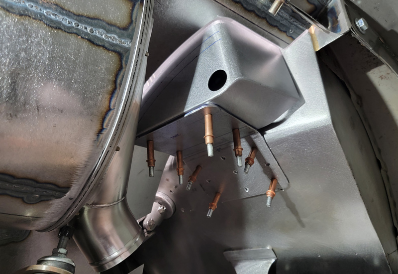
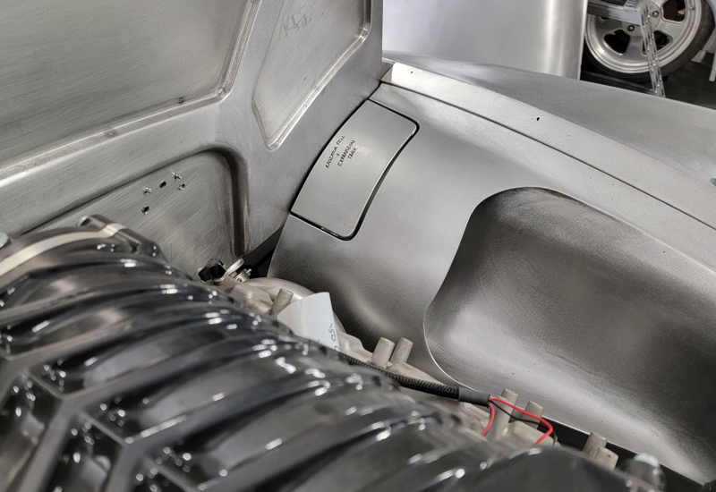
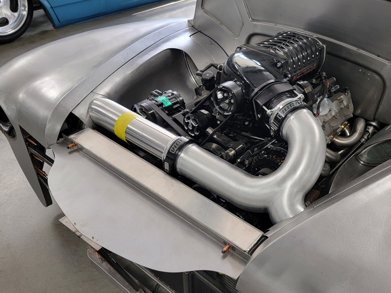
With all of that figured out, I started making the coolant tanks that sit above those heat exchangers. Originally, I had planned on building tanks that would sit above the surface of the inner fenders and go down into the underside of the fender, but no matter what I did, it just didn’t look right. I had asked my friend/coworker Shawn how he felt it would look if I just flush-mounted the tanks into the inner fenders to not detract from the top shape of them. Shawn agreed that would look better, so I started building the tanks flush into the inner fender. The driver side coolant tank is actually the radiator fill and doubles as an expansion tank, and still works via gravity just like any other normal radiator setup. The passenger side coolant tank is a bit larger, and that’s because it’s for the supercharger coolant. The supercharger coolant pump will also be mounted in that area right below the tank to take advantage of being gravity fed as well. From there, -12AN lines will be run from the tank to the pump, to the first heat exchanger, onto the second heat exchanger for maximum cooling, before going up to the port on the back of the Whipple supercharger, then coming back out of the back of the supercharger back into the tank. At the moment I’m still waiting on all of the fittings from Fragola to show up so I can finish up the tanks. With that for the most part complete, I started moving to the air intake. Initially, I really wanted to do an air filter on top of the radiator and do a ram-air style vent as the actual radiator cover. But there were two issues with that. The first was that the 3.0L Whipple supercharger has a throttle body snout that turns toward the driver side instead of facing forward like the 2.9L. This is something that bothered me for symmetry purposes (lots of symmetry in this engine bay) but I just had to deal with it. The much larger problem was space, there wasn’t any. There is hardly any room at all to make a filter box above the radiator, and that alone quickly made me plan out a new place to put the filter. I eventually came up with the idea of mounting the filter box directly to the core support and allowing the fresh air from the front of the truck to go straight through the filter and up through the inner fenders into the throttle body. I pitched that idea to Mark, our amazing mechanic, and he suggested putting a filter on each side of the core support to gain more usable filter surface area and more air, which I didn’t see coming. I wasn’t originally in love with the idea of running a huge 4-inch pipe front and center straight to the other side of the engine bay, but the extra functionality was enough for me to agree. Brian plans on driving the hell out of this truck, so I’ve been doing everything I can to make sure it operates as it should and can take the abuse. Knowing that we could do a speed density tune on the Holley Terminator ECU, and that we had the room to do dual filters, we started making it happen. I just wanted to make sure that the form met the function.
I had Camren order me all of the intake piping and trick clamps from Vibrant Performance, and while those were on the way I started making the air filter boxes and got them mounted. Once parts came in, I had our machinist, Ian, design and machine a throttle body adapter to bolt the Vibrant Performance clamp directly to the throttle body, rather than having to pull the throttle body apart and weld it on. From there, I started building the intake pipe, going to our gas tank builder, Mark, for all the welding. He got everything good and hot so I was able to sand down and metal finish all of the welds on the intake pipe for a really nice, smooth look.
At the time of this writing, the engine bay is still not finished. I still need to make the radiator cover, locate the hood latch, finish the coolant tanks, and make the lower filler panels that go underneath the toeboards to completely close out the engine bay. I’m really proud of this engine bay (I’m really proud of this truck if I’m being honest). It’s definitely been the most detailed and functional one I’ve ever done. There’s a lot going on under those fenders and I think it’s kind of cool that you wouldn’t really know it unless you started looking under the truck. I’m hoping we can take the truck to at least one show in bare metal right before it goes to paint just to show it off, just like we did with the ’65 Cutlass at the Street Rod Nationals.


